
Adjusting to network latency changes

a network latency and network technology, applied in the field of network communication, can solve problems such as failure of a device on the network, increase in network traffic, and increase in rtt to exceed rto, and achieve the effect of fast recovery

Inactive Publication Date: 2008-07-10
MICROSOFT TECH LICENSING LLC
View PDF5 Cites 15 Cited by
  • Summary
  • Abstract
  • Description
  • Claims
  • Application Information

AI Technical Summary

Benefits of technology

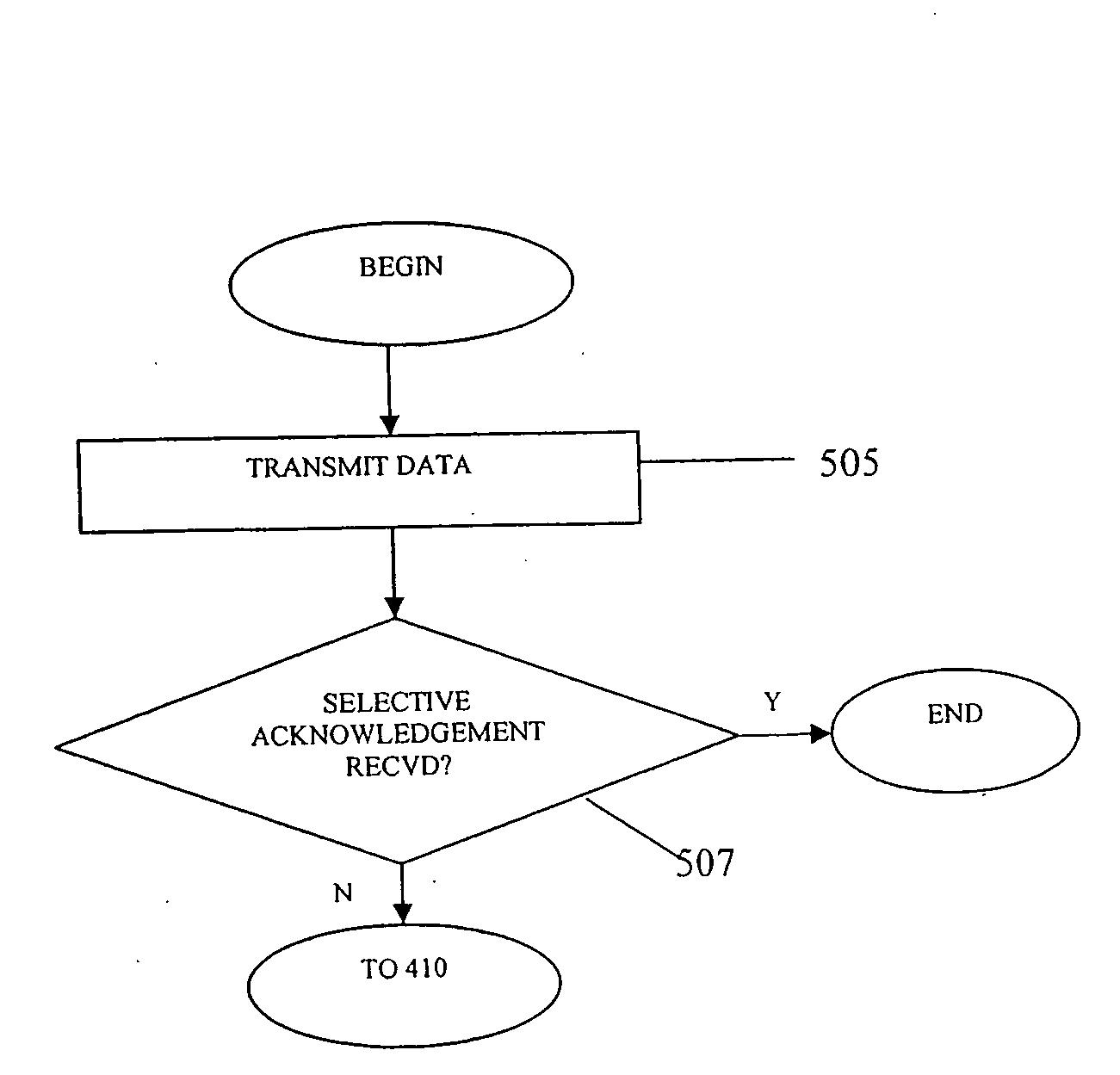
[0011]Some embodiments of the invention may provide a technique enabling fast recovery from changes to network latency. In this respect, some conventional implementations of TCP provide that when a node encounters a retransmission timeout, the node may not send any new data before the previously sent packets are sent and acknowledged. In some embodiments of the invention, a technique is provided which employs an optional capability of the TCP protocol, called forward roundtrip timeout recovery (F-RTO), which enables a new packet to be sent when another packet is retransmitted. Because a new packet is retransmitted, the RTT for the connection may be reliably re-measured, such that a new RTO may be calculated.

Problems solved by technology

Applicants have appreciated that the above-described aspect of TCP which provides that the RTT for a connection is not re-measured if a packet is retransmitted can be problematic when latency for a connection increases dramatically (e.g., caused by a change in the network path between two nodes, an increase in traffic on the network, a failure of a device on the network, etc.), such that, for example, the RTT increases to exceed the RTO.
Because the packet is retransmitted, and because TCP provides that the RTT for the connection is not re-measured for the connection when a packet is retransmitted, the RTO for subsequently transmitted packets is not updated, meaning that the node is likely to encounter a retransmission timeout for each of these packets as well.
As a result, a large number of packets can be retransmitted unnecessarily, and the transmitting node's send rate is significantly decreased, even though packets may not have actually been lost in the network.
In this respect, temporary congestion generally occurs when a particular node on the network transmits a large burst of traffic, causing packets sent by other nodes to be lost.
As such, with temporary congestion, modifications to RTO may be unnecessary.

Method used


Image

  • Adjusting to network latency changes
  • Adjusting to network latency changes
  • Adjusting to network latency changes

Examples


Embodiment Construction

[0019]Some embodiments of the invention provide techniques for recovering from increases to latency on a connection. For example, some embodiments provide techniques for re-measuring the RTT for a connection upon encountering a retransmission timeout, and employing this information when sending new packets. For example, some embodiments provide that if the RTT has changed significantly, a new RTO (or a variation thereof) is defined (e.g., calculated), based on the newly measured RTT, for use with subsequent transmissions on the connection. As a result, the node may be less likely to encounter retransmission timeouts for subsequent transmissions, such that the node is likely to recover more quickly from the retransmission timeout encountered on the original transmission. Conversely, if it is determined that the RTT for the connection has not changed significantly, the RTO for subsequent transmissions on the connection may be defined based on an RTT value which incorporates previously...


PUM


Abstract

Techniques are provided for adjusting to changes to the latency for a connection between two nodes on a network. In accordance with some embodiments, when a transmitting node encounters a retransmission timeout for a packet sent to a receiving node, the latency for the connection is newly measured and used to calculate a new retransmission timeout period for subsequent transmissions by the transmitting node. In some embodiments, the latency is not newly measured if the transmitting node receives a selective acknowledgement from the receiving node, since a selective acknowledgement may indicate that congestion on the network is only temporary.

Description

FIELD OF INVENTION[0001]This invention relates to network communications, and more particularly to managing communications in networks employing the transmission control protocol (TCP).BACKGROUND OF INVENTION[0002]Transmission control protocol (TCP) is widely used for network communications, including communication via the Internet. TCP is a reliable transport protocol, meaning that it provides various mechanisms to ensure that data sent by a transmitting network node arrives intact at a receiving network node. For example, TCP provides that the receiving node sends an acknowledgement to the transmitting node for each data packet received, such that the transmitting node is notified that the packet arrived at the receiving node.[0003]A transmitting node determines that a sent packet has been lost on the network when either duplicate acknowledgements are received from the receiving node, or a retransmission timeout is reached. Briefly, a duplicate acknowledgement is a notification se...

Claims


Application Information

Patent Timeline
IPC IPC(8): H04L12/26
CPCH04L41/0816H04L69/163H04L69/16H04L43/0852
Inventor SRIDHARAN, MURARIKANIYAR, SANJAY N.BANSAL, DEEPAK
Owner MICROSOFT TECH LICENSING LLC
Learn More