Blower housing for climate controlled systems

a technology of climate control and housing, applied in the field of housing, can solve the problems of seat occupants' back and other pressure points being sweaty, vehicle seats becoming very hot and uncomfortable for the occupants, and general discomfort for the seated occupants, so as to reduce the head loss

Inactive Publication Date: 2008-07-10
AMERIGON INC
View PDF0 Cites 203 Cited by
  • Summary
  • Abstract
  • Description
  • Claims
  • Application Information

AI Technical Summary

Benefits of technology

[0010]Another aspect of the present invention comprises a method of facilitating the transfer of a fluid through a filter positioned upstream of a blower inlet. The method includes providing a plurality of protruding members along an outside portion of a blower housing and securing at least a portion of a filter against the protruding members. In some embodiments, the gap created by the protruding members between the filter and the blower housing is configured to reduce the head loss associated with the flow of fluid from outside the blower into an interior portion of the blower.

Problems solved by technology

For example, an automotive vehicle exposed to summer weather conditions, where, for example, the vehicle has been parked in an unshaded area for a long period of time, can cause the vehicle seat to become very hot and uncomfortable for the occupant for some time after entering and using the vehicle, even with normal air conditioning.
Furthermore, even with normal air-conditioning, on a hot day, the seat occupant's back and other pressure points may remain sweaty and generally uncomfortable to the seated occupant.

Method used


Image

  • Blower housing for climate controlled systems
  • Blower housing for climate controlled systems
  • Blower housing for climate controlled systems

Examples


Embodiment Construction

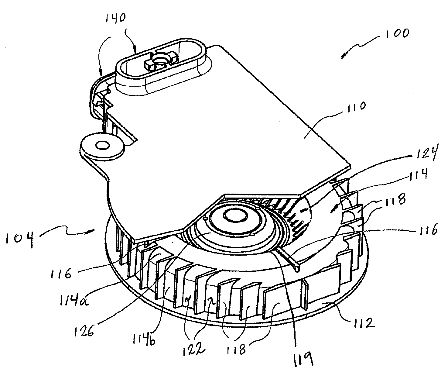
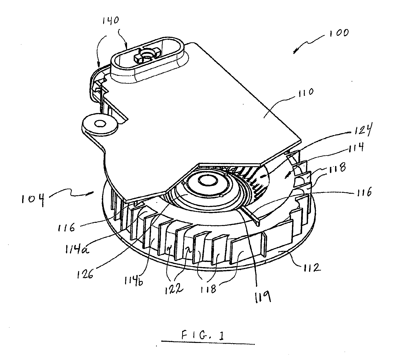
[0021]FIG. 1 illustrates a perspective view of an integrated blower / TED assembly 100 according to one embodiment. The depicted integrated blower / TED assembly 100 is particularly well suited to be used in a climate controlled seating assembly (e.g., automobile chair, wheelchair, theater seats, etc.). The integrated blower / TED assembly 100 preferably includes a radial blower portion 104 and one or more outlets 140 to which TEDs (not shown) can attach. However, the various features and aspects related to the blower disclosed herein can be applied to a blower or other fluid transfer device that is not part of an integrated blower / TED assembly (e.g., a stand-alone blower unit). Further, the blower and its various features described herein may be incorporated into other types of devices, assemblies and systems, such as, for example, beds, sofas, chairs and / or the like, that require a fluid transfer device to convey a volume of air or other fluid to one or more desired locations.

[0022]With...


PUM


Abstract

A blower for use in a climate controlled system includes an outer housing, a plurality of protruding members extending from the outer housing, an inlet opening in the outer housing, an impeller positioned with an internal cavity or space defined by the outer housing and a filter configured for placement against at least some of the protruding members. In some embodiments, the space created by the protruding members between the filter and outer housing facilitates the transfer of air or other fluids into the internal cavity of the blower.

Description

CROSS-REFERENCE TO RELATED APPLICATIONS[0001]This application claims the priority benefit under 35 U.S.C. § 119(e) of U.S. Provisional Application Ser. No. 60 / 884,184, filed Jan. 9, 2007, the entirety of which is hereby incorporated by reference herein.BACKGROUND OF THE INVENTION[0002]1. Field of the Invention[0003]This application relates to climate control systems. More specifically, this application relates to an improved blower to use in climate controlled seating assemblies.[0004]2. Description of the Related Art[0005]Temperature modified air for environmental control of living or working space is typically provided to relatively extensive areas, such as entire buildings, selected offices, or suites of rooms within a building. In the case of vehicles, such as automobiles, the entire vehicle is typically cooled or heated as a unit. There are many situations, however, in which more selective or restrictive air temperature modification is desirable. For example, it is often desira...

Claims


Application Information

Patent Timeline
Patent Type & Authority Applications(United States)
IPC IPC(8): F04D29/70
CPCF04D29/703F04D29/4206
Inventor GIFFIN, STEVE CRAIG
Owner AMERIGON INC
Why Eureka
Try Eureka