Antivibration Support

Inactive Publication Date: 2008-07-17
PAULSTRA CRC
View PDF4 Cites 9 Cited by
  • Summary
  • Abstract
  • Description
  • Claims
  • Application Information

AI Technical Summary

Benefits of technology

[0009]One objective of the present inv

Problems solved by technology

Generally, a hard material is used in order to control large motion, resulting in a high dynamic stiffness and p

Method used


Image

  • Antivibration Support
  • Antivibration Support
  • Antivibration Support

Examples


Example

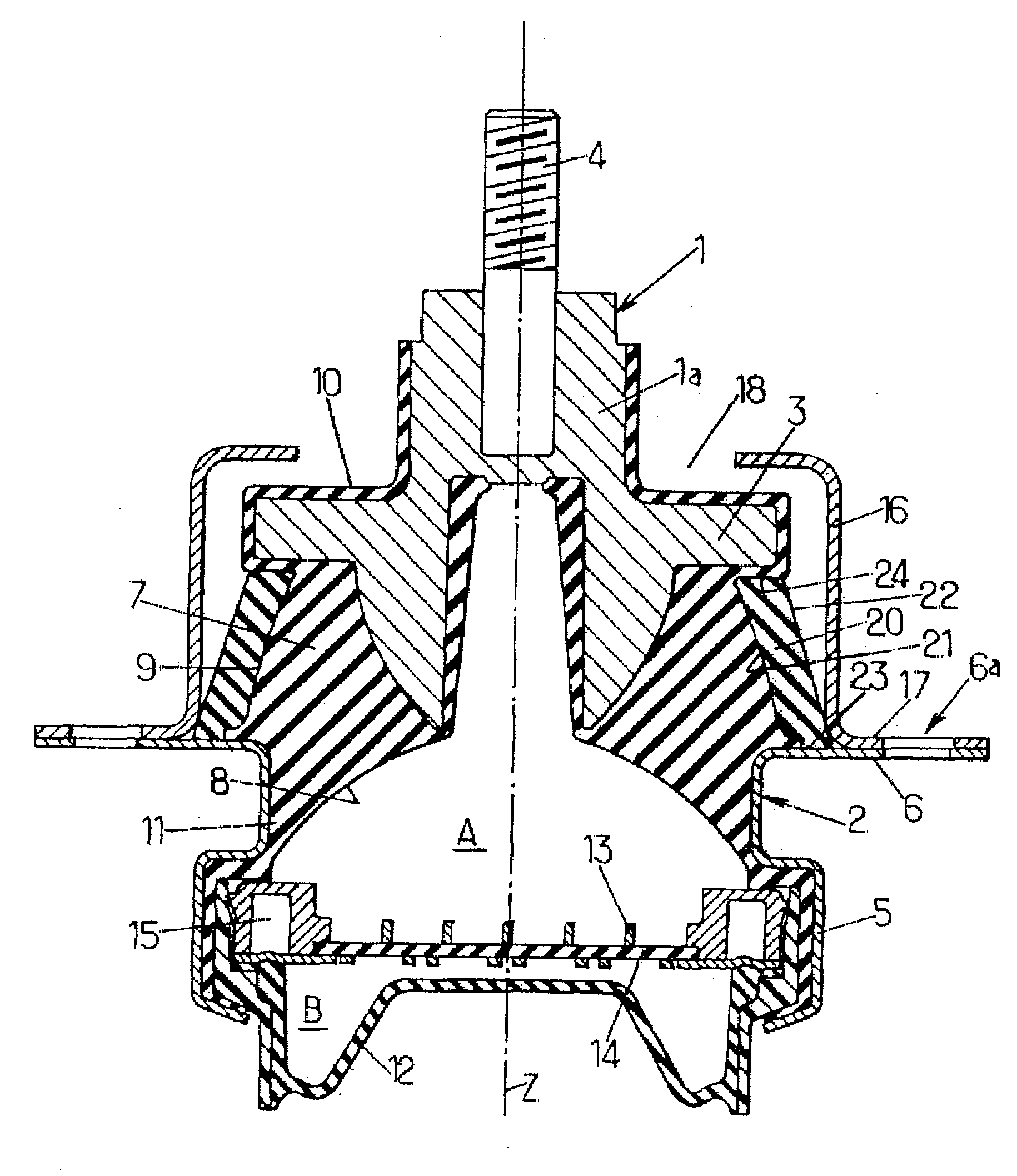
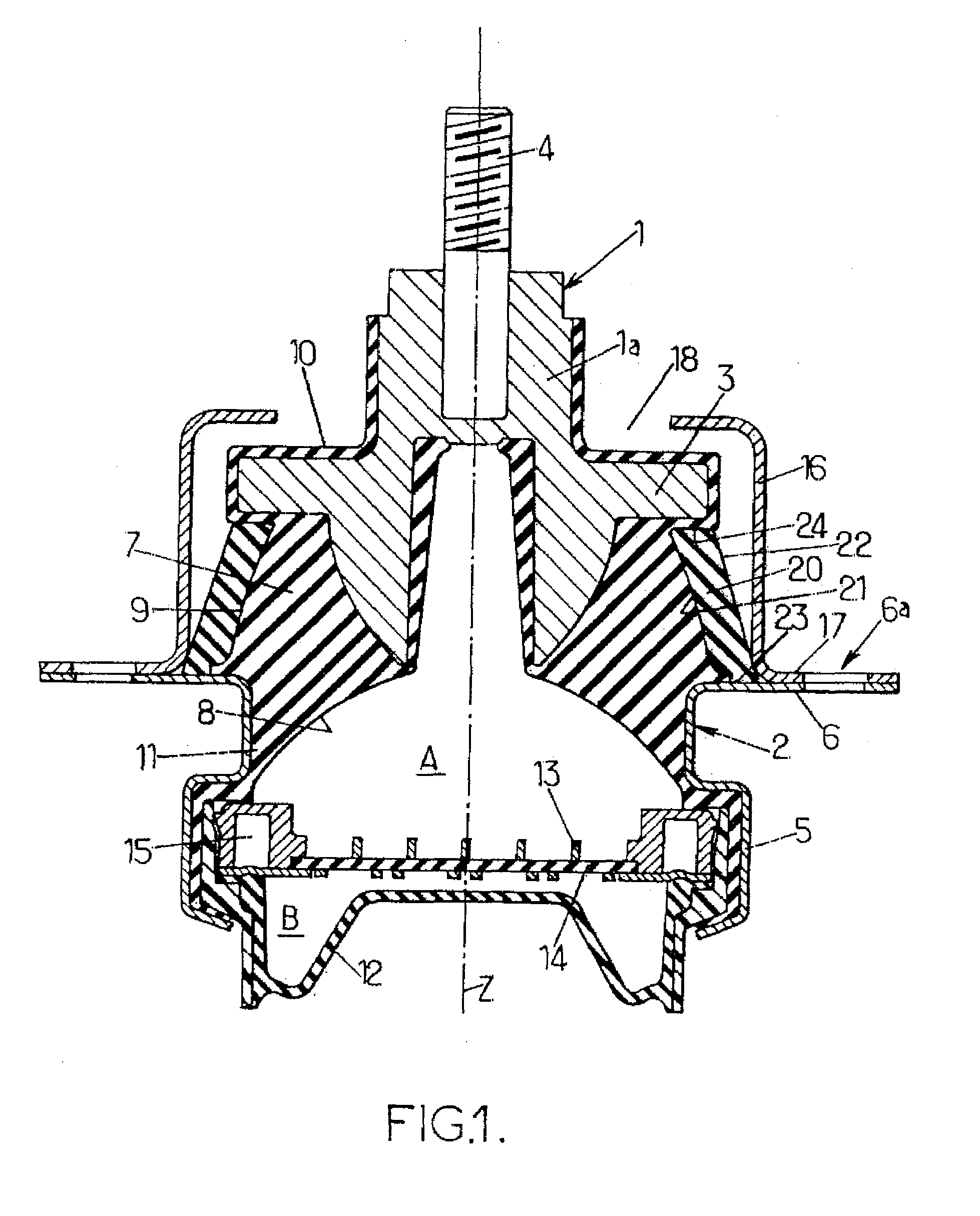
[0037]The hydraulic antivibration device according to a first embodiment of the present invention, and as illustrated in FIG. 1 by way of example, comprises a first rigid strength member 1 and a second rigid strength member 2, extending along a substantially vertical longitudinal axis Z. Both first and second rigid strength members 1, 2 are predisposed to be interposed and attached between external rigid elements for support and dampening. These external rigid elements may for example be a vehicle chassis and an engine (not shown).

[0038]The first rigid strength member 1 comprises a substantially cylindrical body 1a, extending along axis Z. The first rigid strength member further comprises a collar 3 extending outwardly from the cylindrical body 1a, and an upwardly extending stud 4 disposed for fixing, for example, to the engine. The stud 4 may extend upwardly with a slight incline with respect to the vertical axis Z.

[0039]The second rigid strength member 2 takes the form of an annul...


PUM


Abstract

An antivibration support disposed for supporting and dampening loads between external elements, comprising a first and a second rigid member for securing to the external elements, and an elastomer body, connecting respectively the first and second rigid members.
The support also comprises a second body, having dissimilar material properties from the elastomer body, acting in parallel with the elastomer body to support and dampen the loads.

Description

FIELD OF THE INVENTION[0001]The invention relates to antivibration supports.BACKGROUND OF THE INVENTION[0002]More precisely, the invention relates to an antivibration support disposed for supporting and dampening static and dynamic loads between a first and a second rigid element, comprising:[0003]a first rigid member, for securing to said first rigid element;[0004]a second rigid member, for securing to said second rigid element; and[0005]a first body, connected respectively to said first and said second rigid members, said first body being disposed to support said static loads and dampen said dynamic loads[0006]With such supports, it is usually desirable to minimize the dynamic stiffness for better acoustic performance (low vibrational amplitudes and high frequencies), and to have high stiffness in static and high-amplitude events to control large motion.[0007]Generally, a hard material is used in order to control large motion, resulting in a high dynamic stiffness and poor acousti...

Claims


Application Information

Patent Timeline
IPC IPC(8): F16F15/00
CPCF16F13/108F16F3/093
Inventor ADAMS, BLAKE
Owner PAULSTRA CRC
Why Eureka
Try Eureka