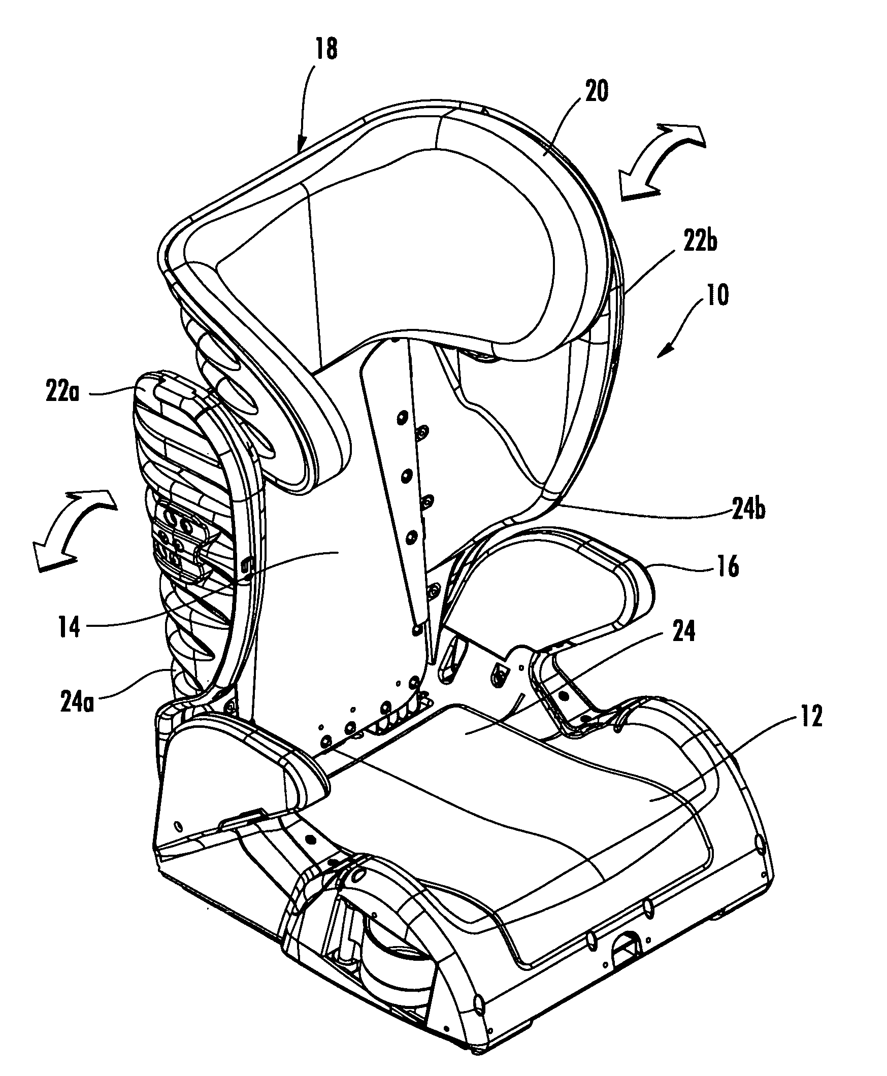
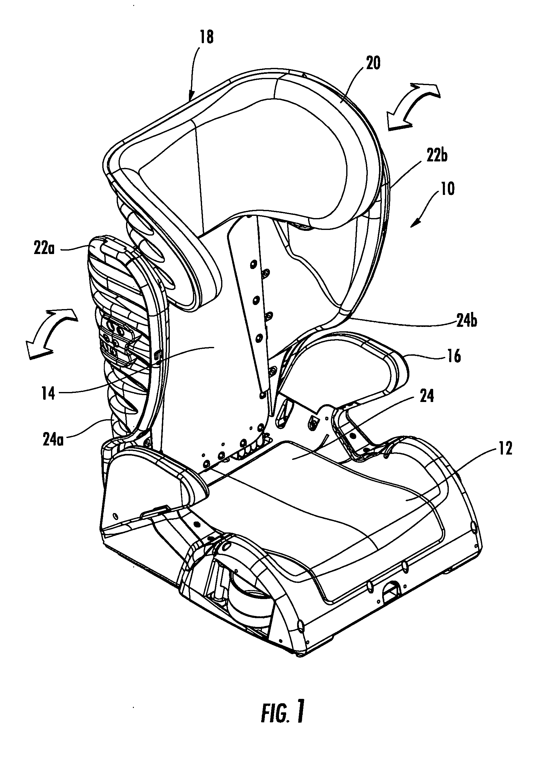
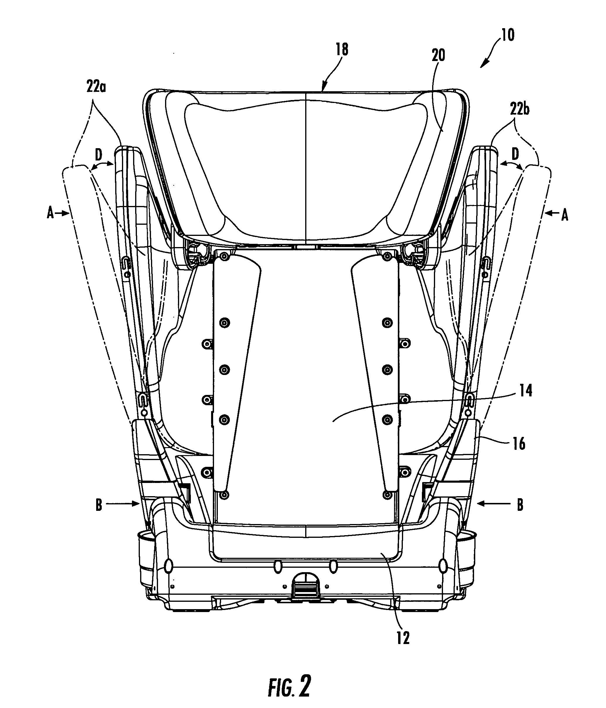
Adjustable child restraint device

a child restraint and adjustable technology, applied in the field of child restraint and safety devices, can solve the problem that the child will soon outgrow the seat, and achieve the effect of convenient adjustmen

Active Publication Date: 2008-07-17
DIONO
View PDF35 Cites 24 Cited by
  • Summary
  • Abstract
  • Description
  • Claims
  • Application Information

AI Technical Summary

Benefits of technology

[0007]The present invention preserves the advantages of prior art child restraint devices, such as child seats and booster seats. In addition, it provides new advantages not found in currently available devices and overcomes many disadvantages of such currently available devices.
[0014]A further object of the present invention is to provide a child restraint device that can be adjusted easily as the child grows to obviate the need to periodically buy a fixed size restraint device.
[0016]Another object of the present invention is to provide a juvenile safety seat that is easily adjustable, such as by one hand of the user.

Problems solved by technology

While these devices may be suitable and fit the child at the time of purchase, the child will soon outgrow the seat requiring the purchase of a new car seat or booster seat.

Method used


Image

  • Adjustable child restraint device
  • Adjustable child restraint device
  • Adjustable child restraint device

Examples


embodiment 100

[0052]FIG. 10 shows a first alternative embodiment 100 of the present invention having a curved guide structure 102 where a tubular member 104, having an inner diameter, is fixed to the seat back 114. Corresponding support members 106a, 106b having a smaller outside diameter or outside size, such as in the form of a tube or rod, are respectively fixed to the side guards 122a, 122b. As can be seen, the support members 106a, 106b slidably actuate in and out of the tubular member 104 fixed to the seat back 114 to provide a desired curved guide structure of the present invention. Of course, a curved rod (not shown) may be fixed to the seat back 114 while the support members are tubes (not shown) that slide over the fixed rod. More than one set of fixed tubular members and support members can be used for additional guiding function. Details of the control knob 126 and rotation thereof for movement is not shown in FIGS. 10-14 for east of illustration thereof.

embodiment 200

[0053]FIG. 11 shows a second alternative embodiment 200 of the present invention that includes a further different type of curved guide structure 202. In this embodiment, a curved slot 204 is located in the seat back 214 to receive pins 204a, 204b respectively on the free ends of support members 206a, 206b respective fixed to the side guards 222a, 222b. Movement of the side guards 222a, 222b in and out are further controlled and guided by the curved guide 202 structure of FIG. 11.

embodiment 300

[0054]Still further, FIG. 12 shows a further embodiment 300 where fixed support members 302a, 302b are respectively attached to the side guards 322a, 322b with pins 304a, 304b positioned on the free ends thereof. The pins 304a, 304b respectively slide within curved slots 306a, 306b in the opposing side guard. The size and position of the support members 302a, 302b and curved slots 306a, 306b are selected to provide the curved guide structure 308 of the present invention.


PUM


Abstract

The present invention provides an adjustable child restraint device, namely, a juvenile safety seat. The safety seat preferably includes a backrest and a pair of side guards that protect the body and shoulder of a person, such as a small child. Each of the pair of side guards have a top end and a bottom end and each are respectively pivotally connected about an axis to the backrest at their bottom ends and movable between a closed position and an open position so that the distance between the respective bottom ends of the side guards remains substantially constant and the distance between the respective top ends of the side guards is adjustable by pivoting movement of the side guards. A curved guide means is disposed in communication with the side guards for guiding movement of the side guards.

Description

CROSS-REFERENCE TO RELATED APPLICATIONS[0001]This application claims priority from prior U.S. Provisional Application Ser. No. 60 / 885,227 filed on Jan. 17, 2007.BACKGROUND OF THE INVENTION[0002]The present invention relates generally to child restraint and safety devices. More specifically, the present invention relates to child restraint and safety devices, such as child car seats and booster seats.[0003]In the prior art, child safety restraints, such as those for use in a vehicle are very well known in the art. Such restraints are secured to an existing vehicle car seat. The child is then secured to the restraint to secure the child during travel. These prior art restraints are typically in the form of a booster seat or a child car seat. A booster seat is commonly known as a seat that attached to an existing vehicle seat where the seat uses the existing belt restraint system of the vehicle. Such a booster seat is commonly used for older children. Also, a child restraint may be in ...

Claims


Application Information

Patent Timeline
Patent Type & Authority Applications(United States)
IPC IPC(8): B60N2/26
CPCB60N2/2851B60N2002/0288B60N2/2872B60N2/2866
Inventor CLEMENT, DAVIDBERGER, RUSSELL
Owner DIONO
Why Eureka
Try Eureka