
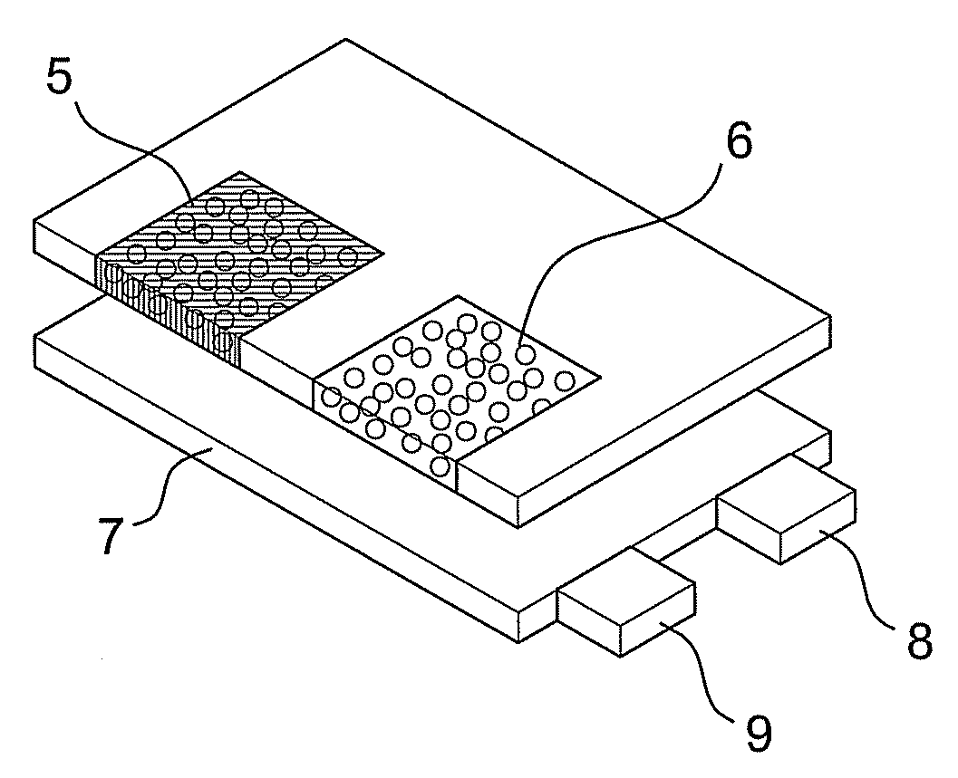
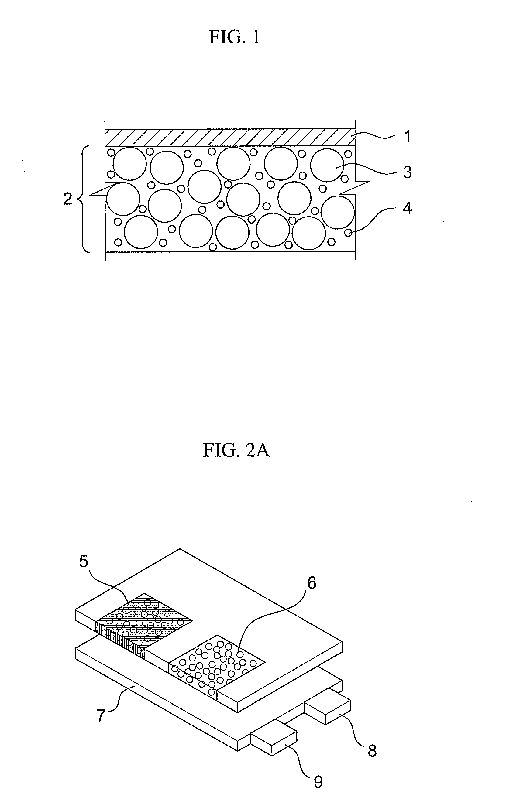
Image display device with plural light emitting diodes

a light-emitting diode and image-based technology, applied in the direction of identification means, static indicating devices, instruments, etc., can solve the problems of copyright problems, color implementation,

Inactive Publication Date: 2008-07-17
SAMSUNG ELECTRONICS CO LTD
View PDF4 Cites 14 Cited by
  • Summary
  • Abstract
  • Description
  • Claims
  • Application Information

AI Technical Summary

Benefits of technology

[0008]An aspect of exemplary embodiments of the present invention is to provide an image display device having a plurality of light emitting diodes (LEDs), which prevents a violet light having a wavelength ranging from about 380

Problems solved by technology

However, such a conventional image display device encounters a problem in that it often does not implement a color which is desired to be expressed.
In particular, in the case of an image display device employing a plurality of light emitting diodes, a phenomenon may be deepened in which a color which is desired to be expressed is not implemented normally and is converted into another colored light at the time of application of a light source of each light emitting diode due to an effect of differ

Method used


Image

  • Image display device with plural light emitting diodes
  • Image display device with plural light emitting diodes
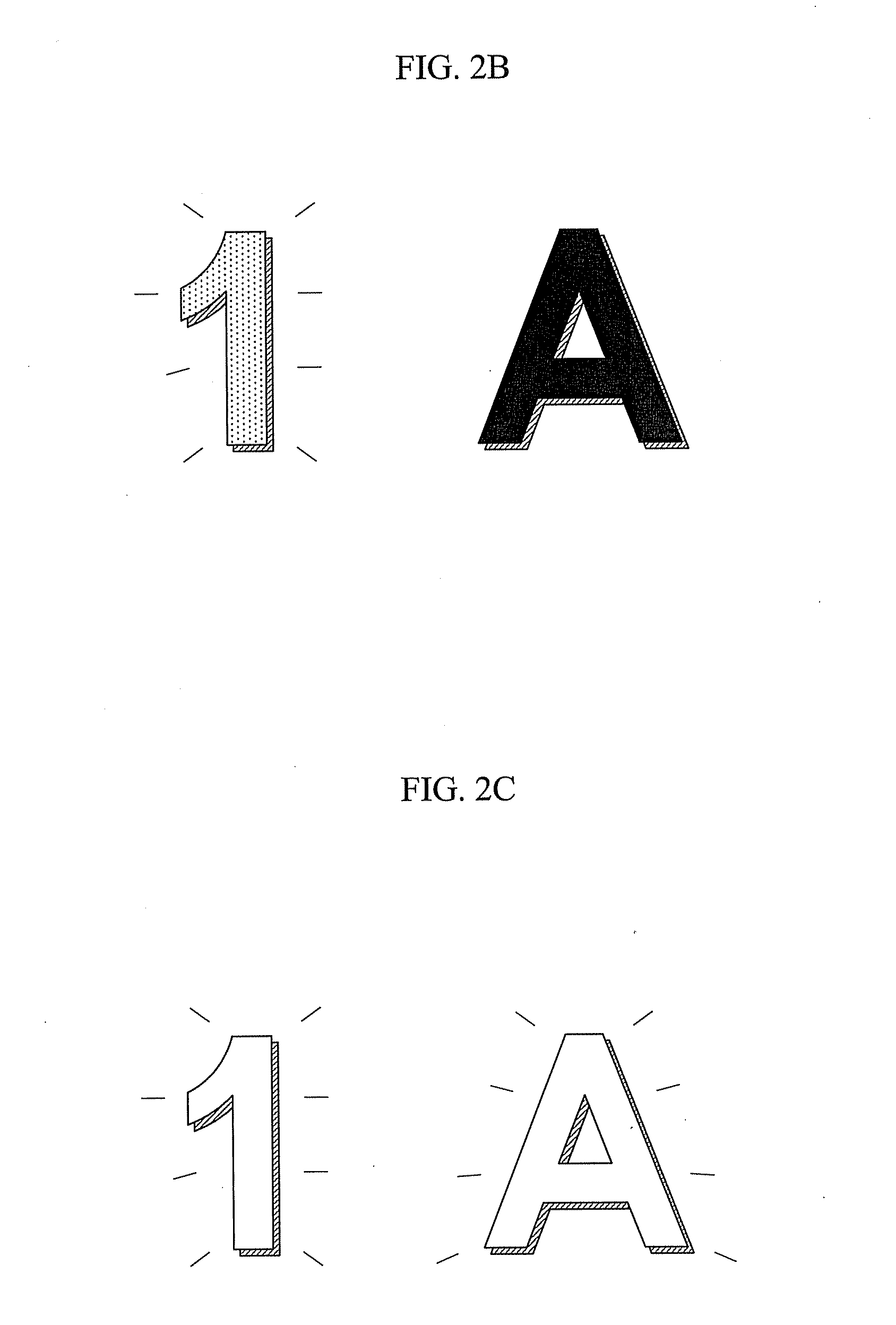
  • Image display device with plural light emitting diodes

Examples


example 1 to 4

Formation of a First Optical Filter Layer Containing Bi2O3

[0049]8.35 g of TiO2, 33.3 g of Bi2O3, 10 g of transparent ink, 18 g of cyclohexane, and balls with a diameter of 1 cm and 0.3 mm were mixed with one another by paint shaking for four hours. Thereafter, a TiO2 / Bi2O3 film was formed as a first optical filter layer using a silk printing method. In the case of the number of TiO2 / Bi2O3 coatings, the number of coatings was set to “2” in Example 1, the number of coatings was set to “3” in Example 2, the number of coatings was set to “4” in Example 3, and the number of coatings was set to “5 in Example 4.

examples 5 to 7

Lamination of the Second Optical Filter Layer

[0054]In Examples 5 to 7, the blue color filter layer as the second optical filter layer is coated in different concentrations on the TiO2 / Bi2O3 film (the number of coatings; 5) as the first optical filter layer fabricated in Example 4 to thereby fabricate a complex optical filter layer. Here, the blue color filter layer was fabricated such that a blue color filter (Inorganic=CoAl2O3) contained in an amount of 20 wt % in a solvent prophylene glycol monomethyl ether acetate (PGMEA) was added to 12.5 g of transparent ink so that the content (wt %) of the blue color filter becomes 1.5 wt % (Example 5), 2.0 wt % (Example 6) and 9.0 wt % (Example 7), respectively, and then, the mixture was distributed with tinky.

experimental example 3

White Color Implementing Effect of the Second Optical Filter Layer

[0055]In Experimental Example 3, in order to confirm white color implementing effect of the second optical filter layer, a complex light filter layer composed of the TiO2 / Bi2O3 film layer (first optical filter layer) and the blue color filter layer fabricated in Examples 5 to 7 was put on the second light emitting diode, i.e., the white light emitting diode, and the intensity of the blue and yellow lights transmitted at the time of light emission from the white light emitting diode was measured (Experimental Examples 3-a to 3-c). Here, the intensity of the light was measured by using Ocean Optics USB 100 detector. A result of the measurement is shown in Table 3 below and FIG. 11.

TABLE 3Color filterBlueYellowBlue / wt %(466 nm)(551 nm)Yellow(TiO2 / Bi2O3wave-wave-ratioExperimentSamplecoatings Fivelengthlength(peak No.No. / times)intensityintensityheight)ExperimentalExample 4047.4748.470.98Example 2-dExperimentalExample 51.54...


PUM


Abstract

Disclosed herein is an image display device having a plurality of light emitting diodes (LEDs), which can maintain a primary color which is desired to be expressed, and prevent an interference of other unwanted colors and a change of the primary color at the time of application of a light source of each light emitting diode. The image display device comprises: a first optical filter layer containing a violet wavelength-absorbing material having a wavelength range of from 380 nm to 450 nm such as Bi2O3 so as to prevent light having a wavelength ranging from 380 nm to 450 nm from being leaked out to an undesired region of an image display portion of the image display device; and a second optical filter layer such as a blue color filter layer so as to allow a white light to be expressed in a desired region of the image display portion.

Description

CROSS-REFERENCE TO RELATED APPLICATION[0001]This application claims the benefit under 35 U.S.C. §119(a) of Korean Patent Application No. 10-2007-0004261, filed in the Korean Intellectual Property Office on Jan. 15, 2007, the entire disclosure of which is incorporated herein by reference.BACKGROUND OF THE INVENTION[0002]1. Field of the Invention[0003]The present invention relates to an image display device, and more particularly to an image display device having a plurality of light emitting diodes (LEDs), which can maintain a primary color which is desired to be expressed and prevent an interference of other unwanted colors, and a change of the primary color at the time of application of a light source of each light emitting diode in the image display device using the plural light emitting diodes.[0004]2. Background of the Related Art[0005]Currently, there has been a constant demand for technological improvement for enhancing system performance in various image display device fields...

Claims


Application Information

Patent Timeline
IPC IPC(8): G09G3/32
CPCG09G3/14G09F9/33H05B33/02H05B33/22
Inventor SHIN, HYEON JINCHOI, JAE YOUNGYI, DONG KEECHOI, SEONG JAEYOON, SEONMI
Owner SAMSUNG ELECTRONICS CO LTD
Learn More