Latch needle for a loop-forming textle

a technology of latching needle and looping, which is applied in the field of latching needle for a loopforming machine, can solve the problems of affecting the casting process, affecting the effect of casting, and affecting the quality of the finished product, so as to reduce the risk of sharp edges in the region of the latching head, the effect of less prone to wear and minimizing potential wear

Active Publication Date: 2008-07-24
GROZ BECKERT KG
View PDF14 Cites 0 Cited by
  • Summary
  • Abstract
  • Description
  • Claims
  • Application Information

AI Technical Summary

Benefits of technology

[0014]In accordance with claim 1, this object is achieved with a latch needle that has the narrowest possible latch spoon. During the casting-off process, this allows the half-loop to be subjected to an at most minimal widening as it slides over the relatively narrow latch head. In addition, due to the reduced width of the latch head, compared with the known latch needles, the distance from the adjacent part (sinker), and thus the risk of contact between the sinker and the latch head, are reduced. The formation of sharp-edged borders on the latch head is avoided. No sharp edges that could damage the threads used for loop formation are formed. In particular, considering the worst case, the separation of threads, i.e., the production of defective goods, with concomitant lines of defects is prevented. The inventive latch needle combines the advantages of the male latch-female hook type needle with the advantages of the small-grooved latch needle.
[0019]The width of the needle shaft is measured perpendicular to said shaft's lateral surfaces. This shaft width substantially corresponds to the width of the needle locator in the knitting machine or is slightly smaller, so that the longitudinal movability of the knitting machine needle is ensured.
[0020]Referring to a latch needle in accordance with the invention, the width of the latch head is preferably substantially smaller than the width of the needle shaft. Preferably, the width of the latch head amounts to 80% of the width of the needle shaft, whereby already the reduction of 5% of the width of the latch head—beginning with the width of the needle shaft—offers substantial advantages regarding distance. Ideally, the width of the latch head ranges between 70% and 90% of the width of the needle shaft. As a result of this, it is ensured that, during the oscillating motion of the latch, there is sufficient space between the lateral surface that limits the latch head and the part of a knitting machine adjacent to said lateral surface.
[0021]Another advantage of a latch head in accordance with the invention is its design. In case of contact with another component of a knitting machine, the parallel lateral surfaces of the latch head offer a surface-like abutment. Compared with a point-like site of contact, such an abutment is less prone to wear, i.e., any potential wear is minimized. Consequently, the risk that sharp edges will form in the region of the latch head has been considerably reduced.

Problems solved by technology

These tolerances increase because of the wear during prolonged use of the knitting machine needle, thus also causing the lateral displacement of the latch to be increased.
In so doing, the sinker, as well as the latch head are worn, which is disadvantageous.
However, the result of this is that, during the casting-off process, the half-loop drags on the part of the hook tip that is not covered by the latch head and, in the worst case, is caught, thus interrupting the casting-off process.
This, in turn, negatively affects the loop formation.
Another disadvantage of a male latch-female hook type needle is that the relatively narrow latch head tends to laterally slide on the hook past the inside space of the hook.
This risk increases with increasing wear of the latch bearing.
A further disadvantage of a male latch-female hook type needle is that the transition from the latch shaft inside to the hook tip is not stepless when the latch is in closed position.
This increases the risk that, in particular when plating, i.e., knitting with two threads, one of these two threads escapes between the closed latch and the hook.
As a result, defective goods are produced.
This solution is used in many cases, whereby the increased size of the latch due to the projection has been found to be disadvantageous, in particular in knitting machines.

Method used


Image

  • Latch needle for a loop-forming textle
  • Latch needle for a loop-forming textle
  • Latch needle for a loop-forming textle

Examples


Embodiment Construction

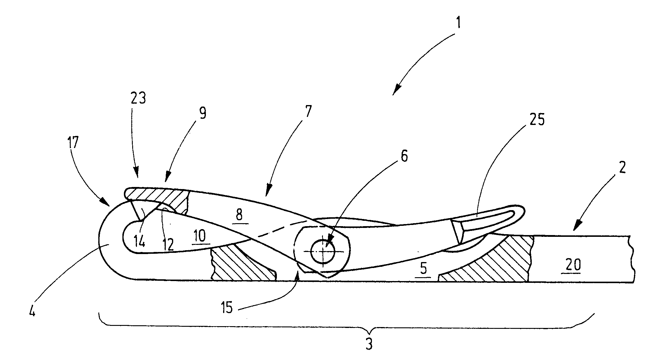
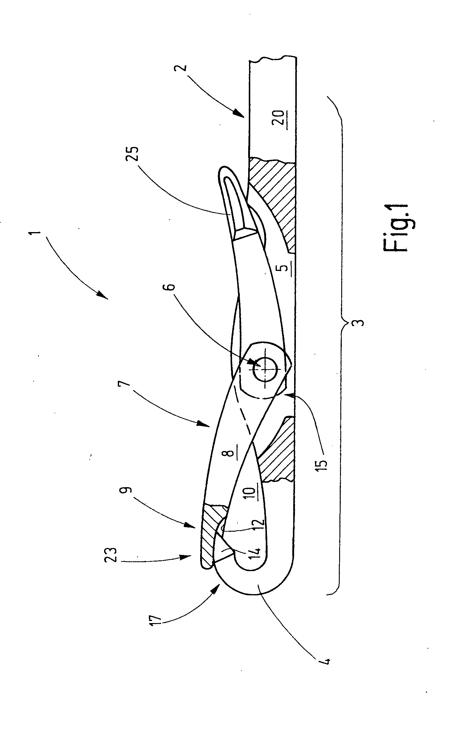
[0032]FIG. 1 shows a latch needle 1, which has a needle body 2 with a loop-forming part 3 having a hook 4 on its end. The hook 4 terminates in a tip 14.

[0033]On its loop-forming part 3, the needle body 2 has a latch slit 5, into which extends an end 15 of the latch 7. The latch 7 is held in the latch slit 5 on a bearing arrangement 6, so as to be pivotally supported. The bearing arrangement 6 consists of a bearing shaft extending through the latch slit 5, for example. This bearing shaft, which may be configured as a bearing pin or, preferably as a one-piece or multi-piece peg that is seamlessly connected with the needle body 2. The latch 7 is supported in such a manner such that it can be pivoted about this bearing arrangement 6 out of the closed position shown on the left side in FIG. 1 and into a rear position shown on the right side in FIG. 1. A hook inside space 10 is closed and opened, respectively, during the change from the closed position into the open position.

[0034]The lat...


PUM


Abstract

A latch needle (1) having on its latch (7) a latch head (9) that is provided with a recess or a depression (12) for receiving a section of a tip (14) of the hook (4), said tip having the configuration of a truncated cone. The latch head (9) is wider than the latch shaft (8) of the latch (7), however, distinctly narrower than the needle shaft (20). Due to this measure, too great an expansion of the loops during the casting-off process is avoided, and the risk of a collision of the latch head with other components, for example, sinkers, is reduced.

Description

CROSS REFERENCE TO RELATED APPLICATION[0001]This application claims the priority of German Patent Application No 06 013 100.0, filed on Jun. 26, 2006, the subject matter of which, in its entirety, is incorporated herein by reference.BACKGROUND TO THE INVENTION[0002]The invention relates to a latch needle for a loop-forming machine, in particular for a knitting machine, for the production of flat textiles.[0003]In order to form loops of a minimum of one thread, so-called latch needles are used in machines, in particular knitting machines, whereby, in operative mode, said needles are moved back and forth in rapid succession. In so doing, the latch provided on such a latch needle opens and closes a receiving space in rapid succession and at high speed. When the latch changes from closed position into the rear position, the latch head performs an oscillating movement in the form of an arc of a circle. In so doing, the latch alternately impacts on the hook in rapid succession in order to...

Claims


Application Information

Patent Timeline
Patent Type & Authority Applications(United States)
IPC IPC(8): D04B35/04
CPCD04B35/04D04B35/00
Inventor BAUSCH, ALBERTSCHMOLL, HANS-WOLFGANGBRAUN, JOCHEN
Owner GROZ BECKERT KG
Why Eureka
Try Eureka