Pneumatic tire

a technology of pneumatic tires and grooves, applied in the field of pneumatic tires, can solve the problems of cracks at the bottom of the second fine groove, and achieve the effects of reducing stress, reducing stress, and reducing the bottom cracking

Inactive Publication Date: 2008-07-24
TOYO TIRE & RUBBER CO LTD
View PDF2 Cites 5 Cited by
  • Summary
  • Abstract
  • Description
  • Claims
  • Application Information

AI Technical Summary

Benefits of technology

[0014]The position of the second fine groove determines the position of the narrowed portion of the thin rib and affects the deformation of the thin rib. Therefore, it is preferable that the distance from the bottom of the first fine groove to the second fine groove (the distance projected on the tire equator surface) is 20% to 50% of the depth of the first fine groove. When this distance is less than 20% of the depth of the first fine groove, since the distance between the narrowed portion and the bott...

Problems solved by technology

However, when the bottom of the second fine groove is on the inner side of the tire width direction than a virtual surface that passes through the grounding end and is ver...

Method used


Image

  • Pneumatic tire
  • Pneumatic tire
  • Pneumatic tire

Examples


example

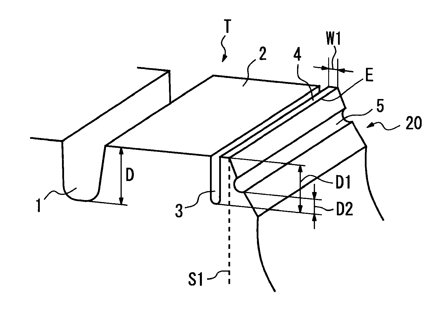
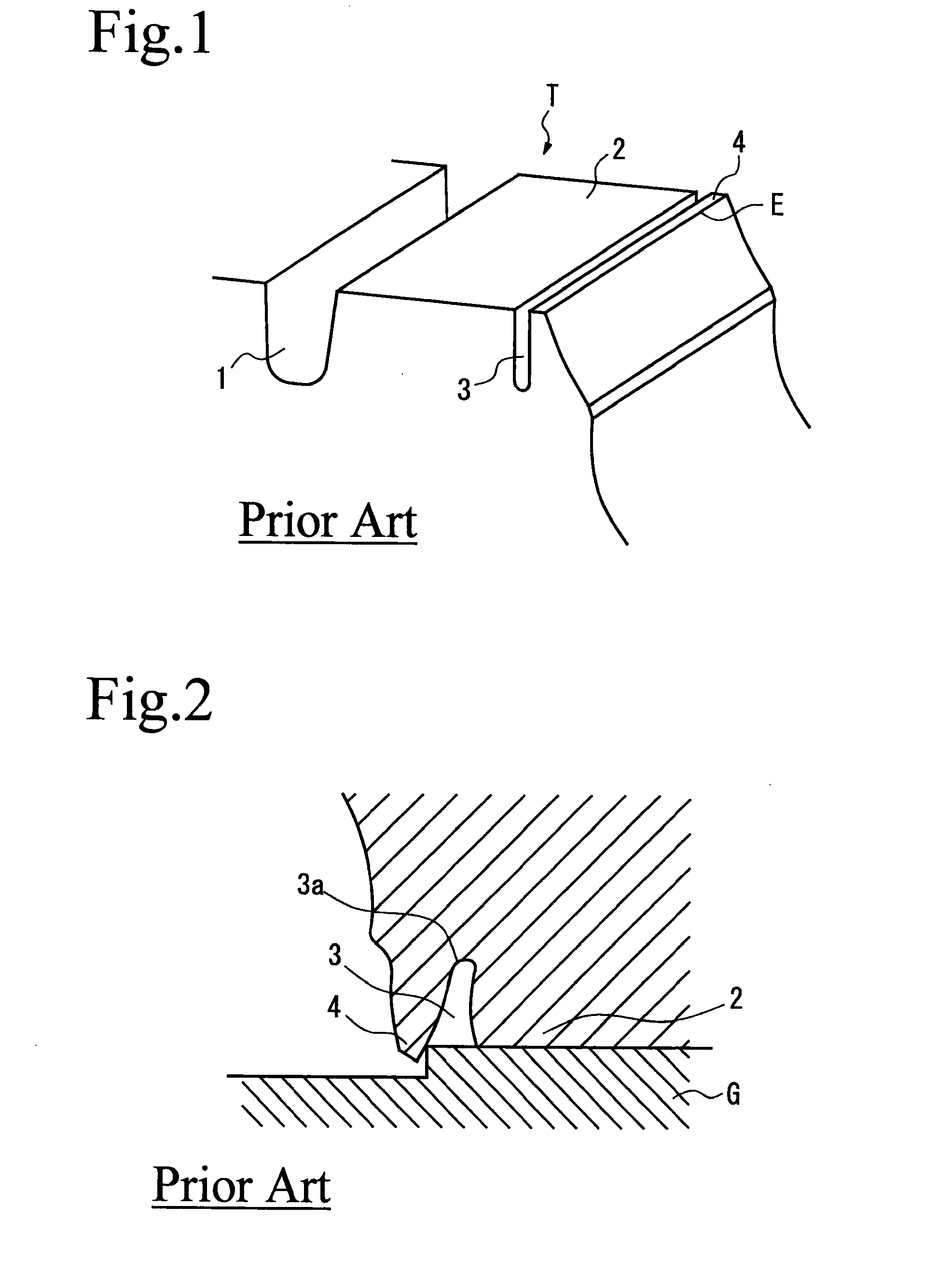
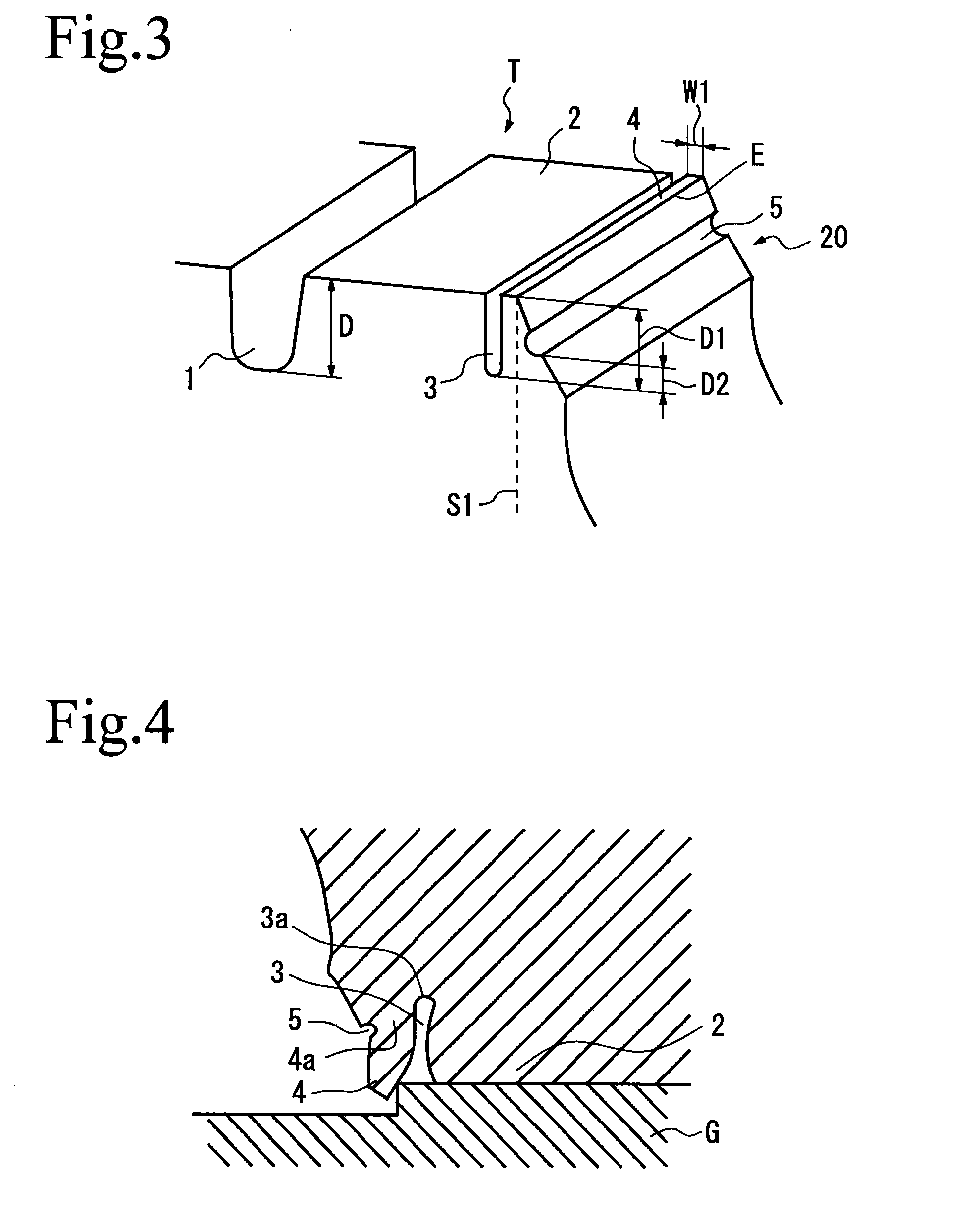
[0029]As Examples, the pneumatic tires of the present invention and those of the Comparative Examples were test produced and the evaluation was made by installing the tires on front wheels of a tractor for towing a trailer (axle arrangement 2D). For information, the tire size was 295 / 75R 22.5 and air pressure was 720 kPa. The tires of the Examples 1 and 2 are for the tires provided with the shoulder portions as shown in FIGS. 3 and 5, respectively, the tire of the Comparative Example 1 is for the tire provided with the shoulder portion as shown in FIG. 1, and the tire of the Comparative Example 2 is for the same tire as in the Example 1 except that the bottom of the second fine groove 5 is on the inner side in the tire width direction than the virtual surface S1.

[0030]The sizes of each of the fine grooves are shown in Table 1. When the distance from the bottom of the second fine groove to the virtual surface S1 is positive, it shows that the groove bottom is on the outer side in the...


PUM


Abstract

The pneumatic tire has the characteristics in that the pneumatic tire is provided with a plurality of main grooves 1 extending in the tire circumferential direction formed on a tread T, a rib 2 formed at least on the shoulder portion of the tread T, a first fine groove 3 extending in the tire circumferential direction formed on the inner side of the tire width direction than a grounding end E, and the thin rib 4 formed by the first fine groove 3 and the grounding end E, wherein a second fine groove 5 is formed on the outer side of the tire width direction than the grounding end E, the second fine groove 5 is on the outer side of the tire width direction than a virtual surface S1 that passes the grounding end E and is vertical to the tire rotational axis.

Description

[0001]The description of this application claims benefit of priority based on Japanese Patent Application No. 2007-9777, the entire same contents of which are incorporated by reference herein.BACKGROUND OF THE INVENTION[0002]1. Field of the Invention[0003]The present invention relates to a pneumatic tire, and in more detail, the present invention relates to the pneumatic tire provided with thin ribs in the vicinity of a grounding end, with inhibited uneven wear at a shoulder portion of a tread.[0004]2. Description of the Prior Art[0005]In pneumatic tires, since grounding pressure at a shoulder portion of a tread gets higher, there used to arise a problem of uneven wear in which the wear amount at the shoulder portion is greater than at the other portions. In order to inhibit such uneven wear, as shown in FIG. 1, a fine groove 3 is formed that extends in the tire circumferential direction from a grounding end E to the inner side in the tire width direction, and a thin rib 4 sandwiche...

Claims


Application Information

Patent Timeline
IPC IPC(8): B60C11/01
CPCB60C11/13B60C11/01
Inventor OHARA, MASAAKI
Owner TOYO TIRE & RUBBER CO LTD
Why Eureka
Try Eureka