Mill and method for drilling composite bridge plugs

Active Publication Date: 2008-07-24
BAKER HUGHES INC
View PDF10 Cites 22 Cited by
  • Summary
  • Abstract
  • Description
  • Claims
  • Application Information

AI Technical Summary

Benefits of technology

[0018]Alternatively, the configuration of the bridge plug may be adapted to improve the circulation flow currents due to the fluid jetted from the central port

Problems solved by technology

The high pressure of the fracturing fluid propagates a fracture in the formation, which may increase the production of hydrocarbons from that zone of the wellbore.
For example, the material of the bridge plug can affect the milling time needed to remove the bridge plug from the wellbore.
Bridge plugs used to be comprised of a material such as cast iron, which is a brittle metal, but is not easy to drill through using a milling assembly run on coiled tubing.
Coiled tubing does not provide as much of a set down weight as prior milling assemblies that used jointed pipes.
Another potential problem with past drillable bridge plugs is the rotation of the bridge plug or the rotation of components within the bridge plug.
However, once the mill has milled out the lower slips of the anchoring assembly, the remainder of the plug falls down the wellbore landing on top of the next bridge plug.
In the past, the remainder of a bridge plug located on the top of lower bridge plug presented another potential problem.
As a result a large amount of proppant may remain within the wellbore between two set bridge plugs.
Current designs o

Method used


Image

  • Mill and method for drilling composite bridge plugs
  • Mill and method for drilling composite bridge plugs
  • Mill and method for drilling composite bridge plugs

Examples


Example

[0024]While the invention is susceptible to various modifications and alternative forms, specific embodiments and methods have been shown by way of example in the drawings and will be described in detail herein. However, it should be understood that the invention is not intended to be limited to the particular forms and methods disclosed. Rather, the intention is to cover all modification, equivalents and alternatives falling within the spirit and scope of the invention as defined by the appended claims.

DETAILED DESCRIPTION OF THE ILLUSTRATED EMBODIMENTS

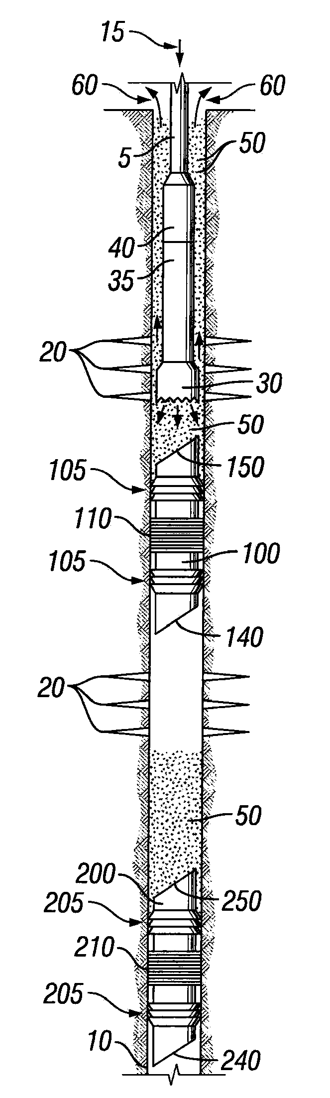
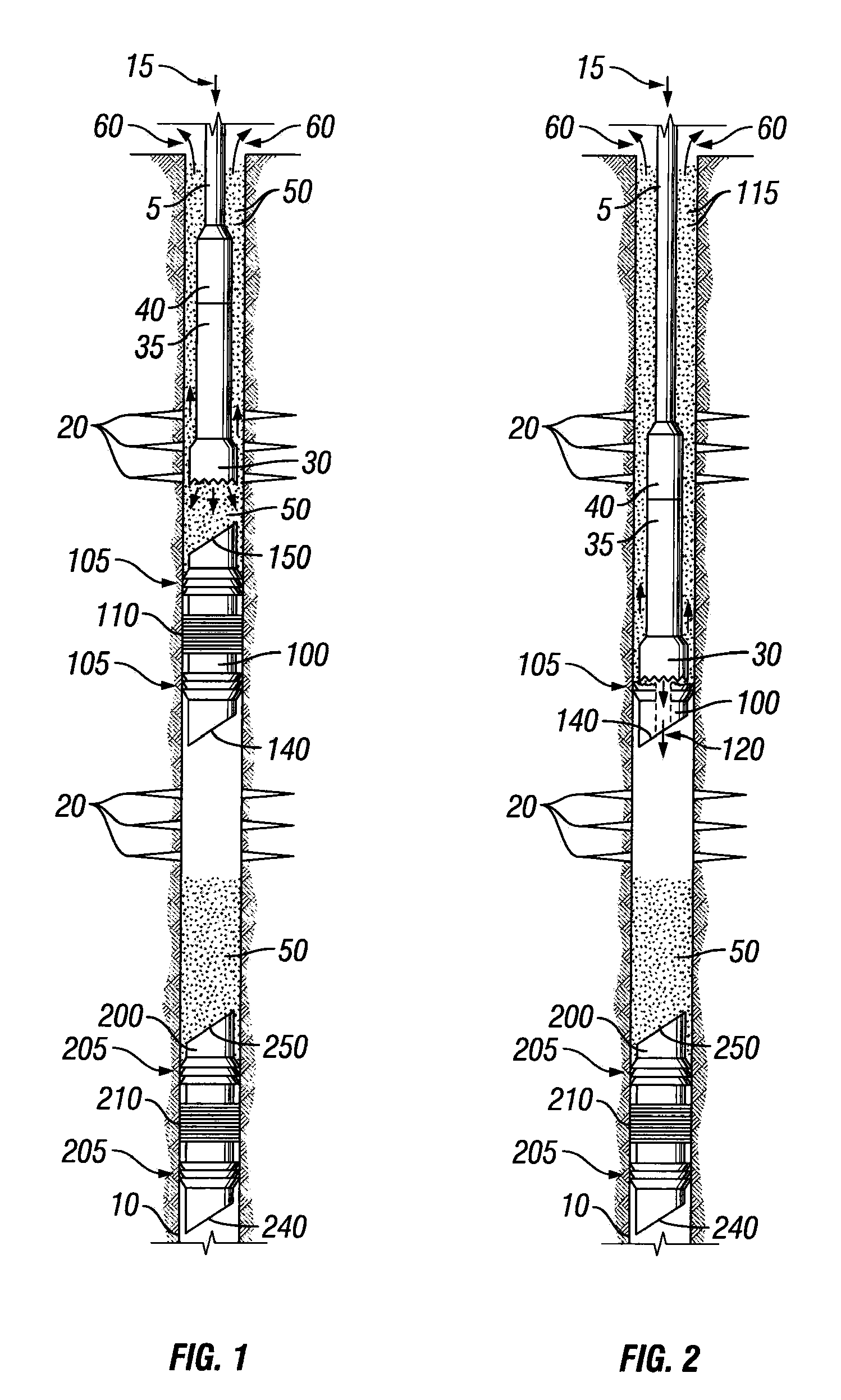
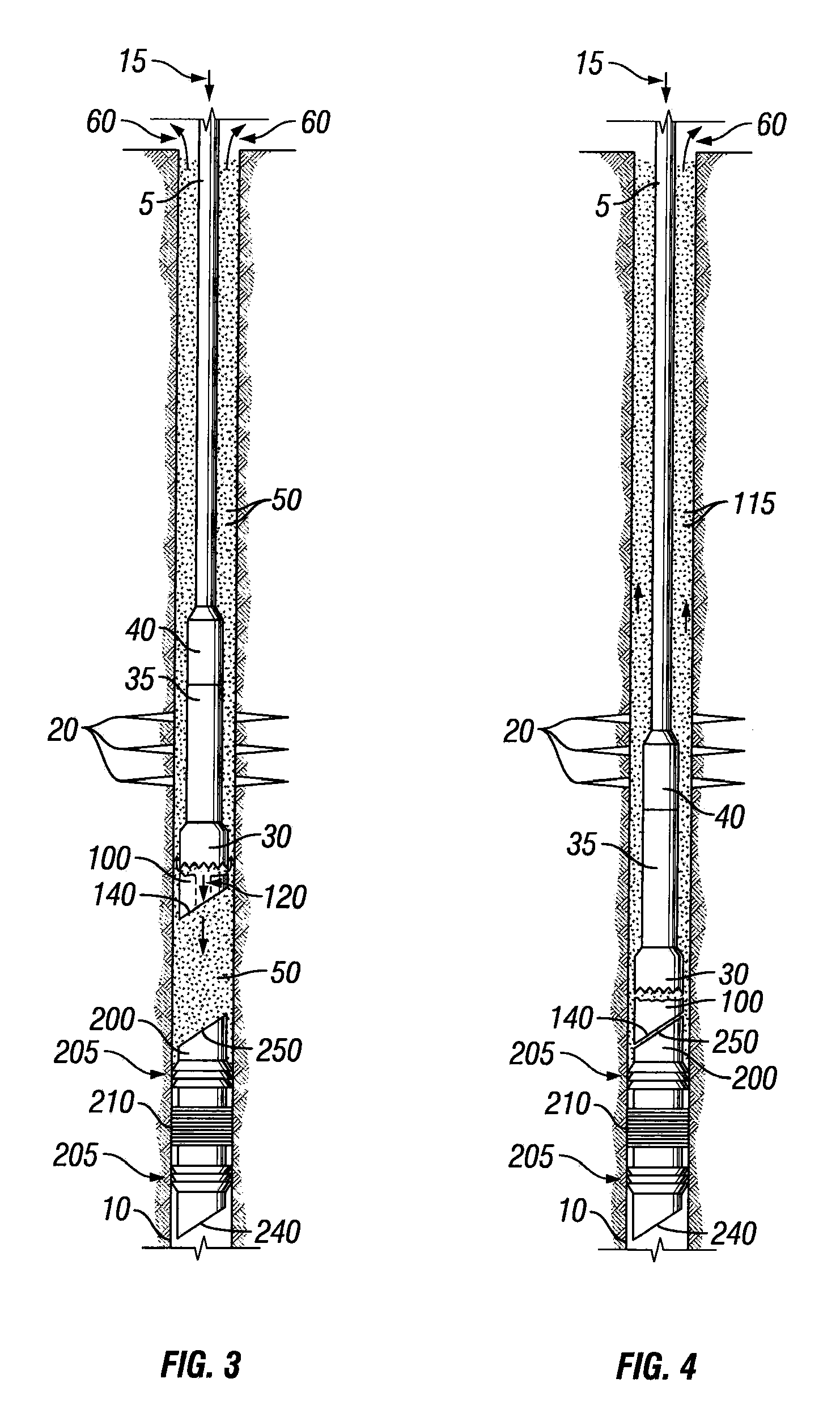
[0025]Illustrative embodiments of the invention are described below as they might be employed in a system and method used to mill a bridge plug from a wellbore, the system and method being efficient in the removal of proppant located below a spinning bridge plug. In the interest of clarity, not all features of an actual implementation are described in this specification. It will of course be appreciated that in the development of any...


PUM


Abstract

A system used to remove multiple isolation plugs from a wellbore. The system is efficient in fluidizing and circulating proppant located below an upper plug resting on top of proppant settled above a lower plug. The system uses a central port of the mill that is in communication with coiled tubing to fluidize and circulate the proppant around the perimeter of the upper plug. Once the proppant has been circulated from underneath the upper plug, the upper plug may mate and rotationally lock with a lower plug set within the wellbore. Upon locking, the system is able to rapidly mill out the upper plug and the lower plug until the lower plug is no longer set within the wellbore. The system provides for the rapid removal of multiple plugs positioned within a wellbore where an amount of proppant is present between the plugs.

Description

PRIORITY[0001]This application claims the benefit of U.S. Provisional Application No. 60 / 881,093, filed on Jan. 18, 2007, entitled “IMPROVED MILL FOR DRILLING COMPOSITE BRIDGE PLUGS,” which is hereby incorporated by reference in its entirety.BACKGROUND OF THE INVENTION[0002]1. Field of the Invention[0003]The present invention generally relates to a system that may be used to remove multiple plugs from a wellbore. Specifically, the system of the present disclosure is efficient in fluidizing and circulating proppant located below a portion of an upper plug that rests on a proppant that has settled on top of a lower plug. The proppant causes the partially milled upper plug to spin within the wellbore as the mill turns. The system uses a central port in a mill to fluidize and circulate the settled proppant around the perimeter of the upper plug until the upper plug is able to mate and rotationally lock with a lower plug set within the wellbore. Upon locking, the system is able to rapidl...

Claims


Application Information

Patent Timeline
IPC IPC(8): E21B21/00
CPCE21B29/00
Inventor MISSELBROOK, JOHN GORDON
Owner BAKER HUGHES INC
Why Eureka
Try Eureka