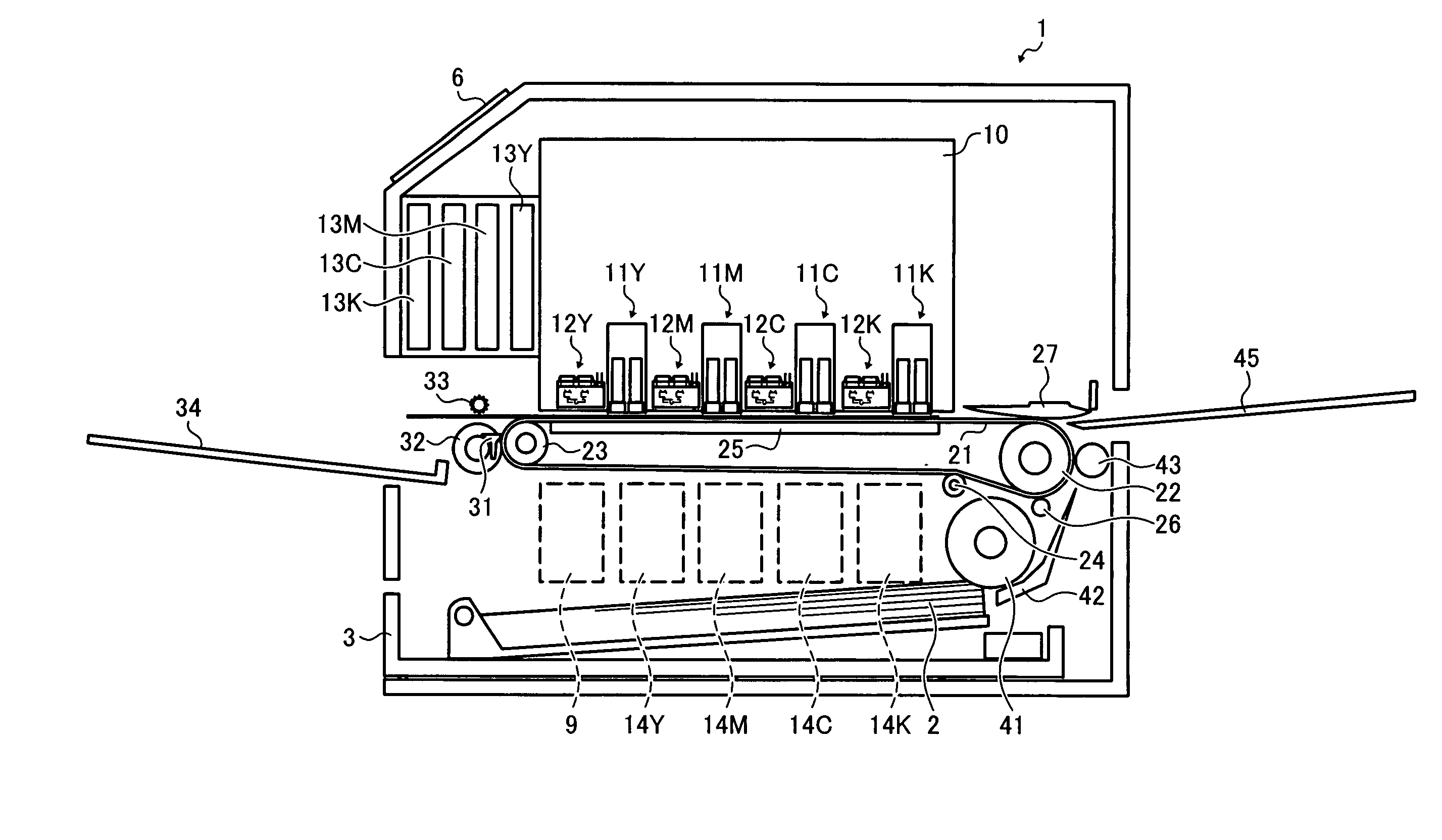
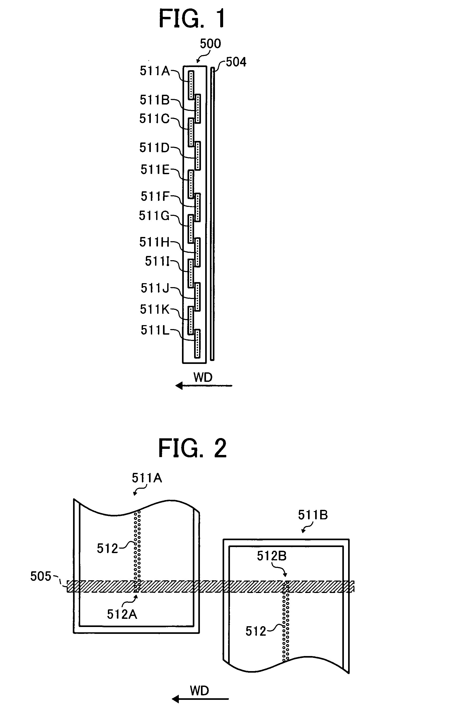
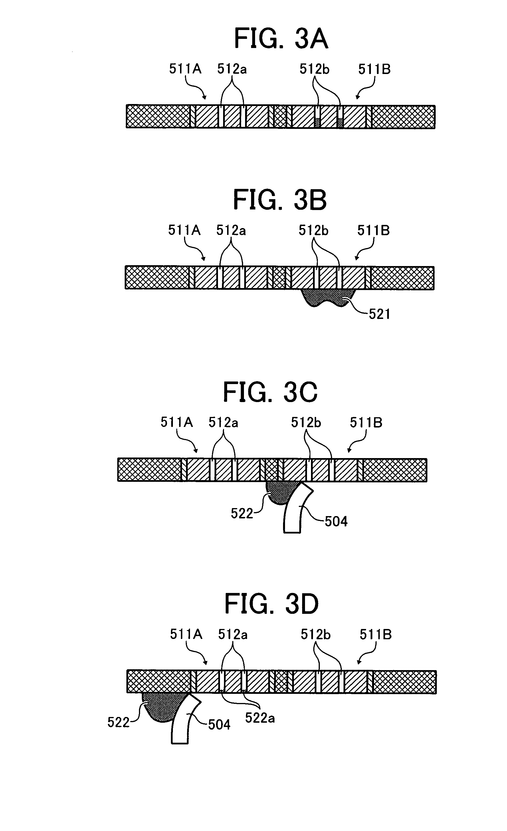
Image forming apparatus having a plurality of liquid discharge heads

a technology of liquid discharge head and image forming apparatus, which is applied in printing and other directions, can solve the problems of clogging of nozzles, discharge failure, and difficulty in maintaining nozzle orifices in a normal operation state, and achieve the effect of less waste liquid

Inactive Publication Date: 2008-07-24
RICOH KK
View PDF8 Cites 32 Cited by
  • Summary
  • Abstract
  • Description
  • Claims
  • Application Information

AI Technical Summary

Benefits of technology

[0018]The present disclosure provides an image forming apparatus capable of reliably recovering from a discharge failure with less waste liquid.

Problems solved by technology

When liquid droplets are discharged from nozzles of such a liquid discharge head, residual liquid, dust, or other foreign matter may adhere on a nozzle formation face of the liquid discharge head, resulting in clogging of the nozzles.
Alternatively, air bubbles generated in the nozzles may result in discharge failures.
Such liquid discharge heads may discharge liquid droplets through minute nozzle orifices having a diameter of, for example, 50 μm or less, and thus it may be difficult to maintain the nozzle orifices in a normal operational state.
In particular, some line-type head units have hundreds or thousands of nozzles, making it more difficult to maintain all the nozzles in a normal state while avoiding various discharge failures.
Consequently, a portion of the ink ejected to the nozzle face may be attached to the wiping member and may be intruded into a nozzle of the normal head, thereby resulting in a discharge failure in the normal nozzle.
In such a head unit, an increase in the nozzle density may make it more difficult to separately wipe the liquid discharge heads.
Consequently, a normal head may be wiped together with a failed head, resulting in a failure in one or more additional nozzles of the normal head.
Further, if ink is absent from a nozzle face during the wiping operation, the function of the ink as lubricant is unavailable.
Consequently, the friction between the wiping member and the nozzle face might be increased, resulting in wear-out of one end surface of the wiping member in contact with the nozzle face, or deterioration or peeling of a water-shedding coating on the nozzle face.
In such a recovery method, a normal head and a failed head are equally suctioned, thereby increasing waste ink.
Further, such an increase of waste ink increases the number of times of replacement of the waste liquid container, thereby imposing more load on the environment.

Method used


Image

  • Image forming apparatus having a plurality of liquid discharge heads
  • Image forming apparatus having a plurality of liquid discharge heads
  • Image forming apparatus having a plurality of liquid discharge heads

Examples


Embodiment Construction

[0086]In describing exemplary embodiments illustrated in the drawings, specific terminology is employed for the sake of clarity. However, the disclosure of this patent specification is not intended to be limited to the specific terminology so selected and it is to be understood that each specific element includes all technical equivalents that operate in a similar manner. For the sake of simplicity, the same reference numerals are used in the drawings and the descriptions for the same materials and constituent parts having the same functions, and redundant descriptions thereof are omitted.

[0087]Exemplary embodiments of the present disclosure are now described below with reference to the accompanying drawings. It should be noted that, in a later-described comparative example, exemplary embodiment, and alternative example, the same reference numerals are used for the same constituent elements such as parts and materials having the same functions, and redundant descriptions thereof are...


PUM


Abstract

An image forming apparatus includes a head unit, a cap unit, a suction device, a wiper unit, and a control unit. The head unit includes a plurality of liquid discharge heads, each having a nozzle face on which a plurality of nozzles are formed. The cap unit caps the nozzle faces of the liquid discharge heads. The suction device suctions an inside of the cap unit while the nozzle faces are capped with the cap unit. The wiper unit wipes the nozzle faces in a manner that a portion of one nozzle face is wiped after a portion of another nozzle face is wiped. The control unit controls a maintenance operation of the liquid discharge heads by selecting a first ejection operation to eject a first amount of liquid and a second ejection operation to eject a second amount of liquid, which is less than the first amount.

Description

TECHNICAL FIELD[0001]The following disclosure relates generally to image forming apparatuses, and more specifically, an image forming apparatus having a plurality of liquid discharge heads.DESCRIPTION OF RELATED ART[0002]An image forming apparatus used as a printer, facsimile machine, copier, or multi-functional device may have a liquid discharge device including a recording head configured as, for example, a liquid discharge head for discharging droplets of a recording liquid (for example, ink). Such image forming apparatuses discharge droplets from nozzles of the liquid discharge head to form a desired image on a recording medium (hereinafter “sheet” or “sheets”).[0003]When liquid droplets are discharged from nozzles of such a liquid discharge head, residual liquid, dust, or other foreign matter may adhere on a nozzle formation face of the liquid discharge head, resulting in clogging of the nozzles. Alternatively, air bubbles generated in the nozzles may result in discharge failur...

Claims


Application Information

Patent Timeline
Patent Type & Authority Applications(United States)
IPC IPC(8): B41J2/165
CPCB41J2/16579B41J2/2146B41J2/16585
Inventor HABASHI, HISASHI
Owner RICOH KK
Why Eureka
Try Eureka