Cushioning mechanism for a treadmill

a technology of cushioning mechanism and treadmill, which is applied in the direction of gymnastic exercise, sport apparatus, cardiovascular exercise devices, etc., can solve the problems of affecting the effect of the exercise, the construction is prone to trouble with respect to assembly, maintenance and replacement, and the platform often frustrates the do-it-yourselfer, so as to achieve the effect of restoring effect, easy assembly and considerably simplifying maintenance and replacement operations

Inactive Publication Date: 2008-07-24
WANG LEAO
View PDF10 Cites 28 Cited by
  • Summary
  • Abstract
  • Description
  • Claims
  • Application Information

AI Technical Summary

Benefits of technology

[0007]Thus, based on the above described drawbacks of the prior art, the designer would like to employ a mechanism exposed to the outside of the main body of the treadmill for an easy assembly while achieving the same effects. In this way, maintenance and replacement operations can be considerably simplified. Thus, a pair of ⊃-shaped rigid connection elements and a pair of pivotal rigid cushioning elements that are interposed between the bottom surface of both sides of the platform frame and the base bars. Moreover, an auxiliary supporting element is pivotally interposed between both sides of the platform frame and the handle frame assembly, respectively. As a result, a complete cushioning and restoring effect can be ensured. In this way, the drawbacks of the prior art in use can be eliminated. This is the main object of the invention.
[0008]Another object of the invention is to provide the means such that the user can adjust the cushioning force of the cushioning element by himself. In this way, the user can perform an operator-oriented adjustment according to personal operation habits for ensuring a comfortable operation. Accordingly, a resistance-adjusting element is provided at the bottom of the guidewheel. A free personal adjustment of the cushioning force may be achieved by the inclination of the resistance-adjusting element 42.

Problems solved by technology

A reaction force will, in turn, act on the feet of the operator, thereby giving him a little discomfort now and again.
However, the aforementioned construction is prone to trouble with respect to its assembly, maintenance, and replacement.
In particular, the disassembly and assembly of the continuous moving belt and the platform often frustrate do-it-yourselfers during the maintenance of the treadmill.

Method used


Image

  • Cushioning mechanism for a treadmill
  • Cushioning mechanism for a treadmill
  • Cushioning mechanism for a treadmill

Examples


Embodiment Construction

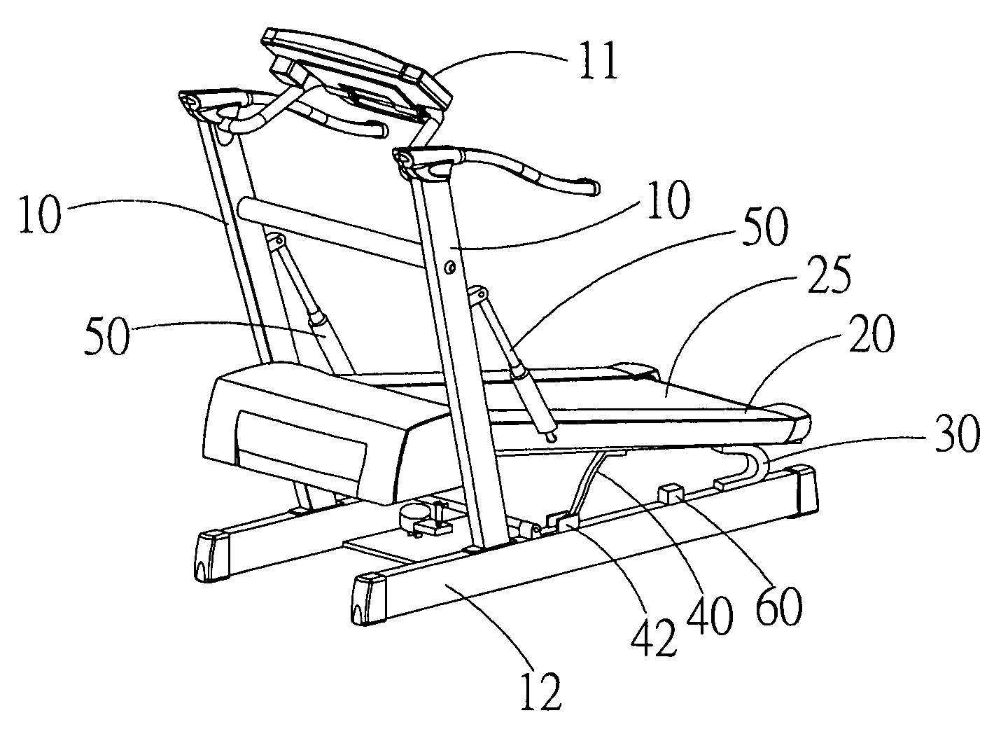
[0016]Referring to FIGS. 1, 2 and 3, a treadmill in accordance with the invention includes a handle frame assembly 10 and a platform frame 20.

[0017]The handle frame assembly 10 is positioned at both sides of a front end of the platform frame 20. An electronic console 11 is installed at a top side of the handle frame assembly 10 while two base bars 12 are attached to a bottom end of the handle frame assembly 10.

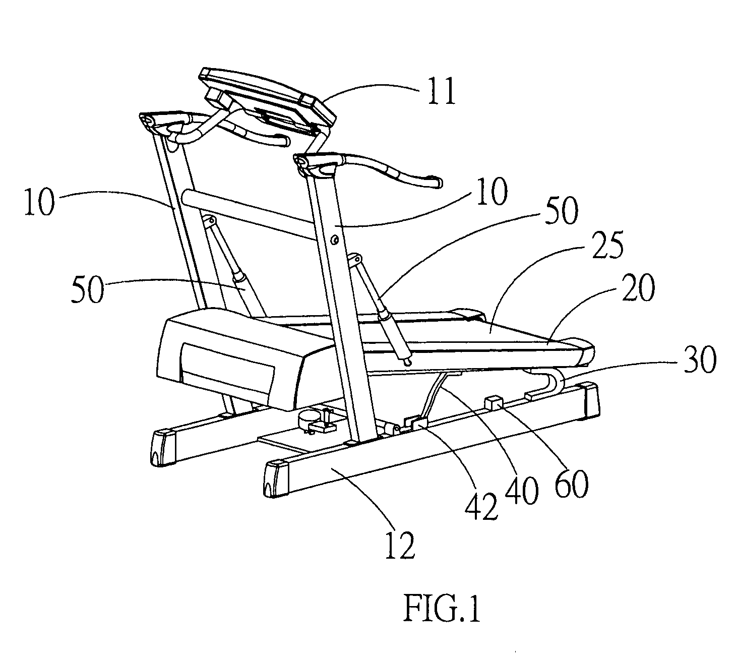
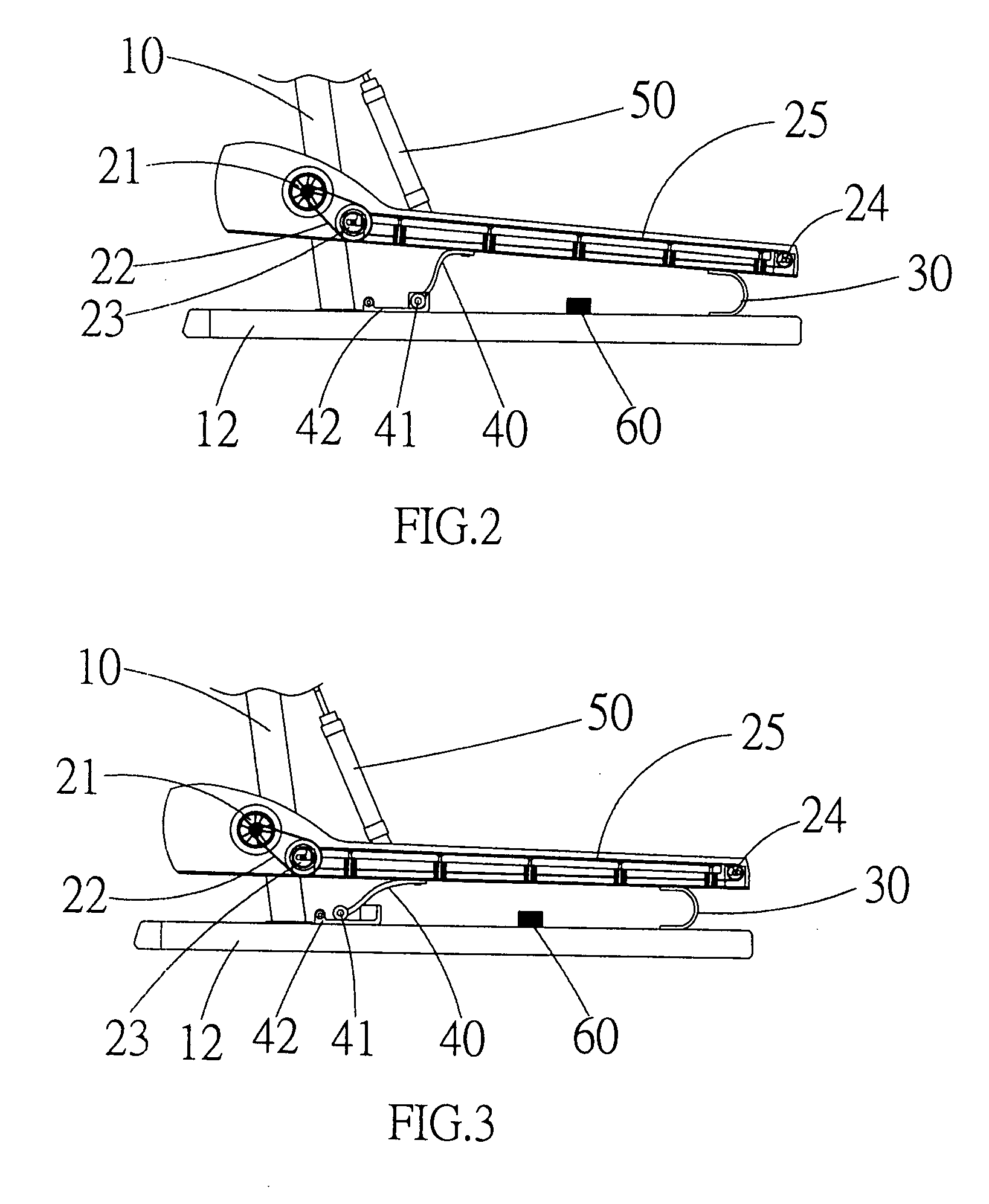
[0018]The platform frame 20 is pivotally mounted near a bottom portion of the handle frame assembly 10. A continuous moving belt 25 works in cooperation with a motor 21, a belt 22, a front roller 23, and a rear roller 24 to ensure a circulating operation.

[0019]A pair of ⊃-shaped rigid connection elements 30 and a pair of pivotal rigid cushioning elements 40 are interposed between the bottom surface of both sides of the platform frame 20 and the base bars 12. The pivotal rigid cushioning element 40 includes a guidewheel 41 at one end thereof. In this way, the guidewheel 41 is m...


PUM


Abstract

A cushioning mechanism for a treadmill having a pair of ⊃-shaped rigid connection elements and a pair of pivotal rigid cushioning elements that are interposed between the bottom surface of both sides of the platform frame and the base bars. The pivotal rigid cushioning element includes a guidewheel at one end thereof. In this way, the guidewheel is movable on the surface of the base bar when the platform frame is moved up and down by the external forces applied to it. Accordingly, the cushioning and restoring effects can be achieved. Moreover, a resistance-adjusting element is provided at the bottom of the guidewheel. A free adjustment of the cushioning force may be achieved by the inclination of the resistance-adjusting element.

Description

BACKGROUND OF THE INVENTION[0001]1. Field of the invention[0002]The invention relates to a cushioning mechanism for a treadmill, and more particularly, to a cushioning mechanism having a compact configuration while achieving an optimal shock-absorbing effect.[0003]2. Description of the Prior Art[0004]A cushioning mechanism of a treadmill is adapted to support a platform frame. A vibration action is created when the platform frame is exposed to a continuous treading force by an operator thereon. A reaction force will, in turn, act on the feet of the operator, thereby giving him a little discomfort now and again. This discomfort can be relieved by the cushioning mechanism.[0005]Accordingly, a few rows of resilient pads are provided between the platform frame and the base frame of the treadmill to achieve an expected shock-absorbing effect. Such a conventional configuration can be easily obtained from e.g. U.S. Pat. Nos. 6,07,7200, 5,746,682, etc.[0006]However, the aforementioned const...

Claims


Application Information

Patent Timeline
Patent Type & Authority Applications(United States)
IPC IPC(8): A63B22/02
CPCA63B2022/0214A63B22/0235A63B22/0214
Inventor WANG, LEAO
Owner WANG LEAO
Why Eureka
Try Eureka