Test pattern generation circuit having plural pseudo random number generation circuits supplied with clock signals at different timing respectively

a technology of pseudo random number generation and test pattern, which is applied in the direction of generating/distributing signals, error detection/correction, instruments, etc., can solve the problems of inability to set multiple seed values, inability to detect/correct errors, and inability to malfunction in interface circuits connected to bus wiring. achieve high test coverage, improve both the randomness of data sequence direction and randomness, and improve the effect of test coverag

Inactive Publication Date: 2008-07-24
RENESAS ELECTRONICS CORP
View PDF6 Cites 16 Cited by
  • Summary
  • Abstract
  • Description
  • Claims
  • Application Information

AI Technical Summary

Benefits of technology

[0012]Moreover, a test circuit includes the test pattern generation circuit of the present invention, a comparator and a result holding circuit. The comparator compares pseudo random numbers inputted via the interface circuit, with pseudo random numbers outputted by the plurality of pseudo random number generation circuits. The result holding circuit holds test results outputted by the comparator and outp

Problems solved by technology

Among malfunctions in a semiconductor device, a malfunction in an interface circuit connected to a bus wiring has been a problem in recent years.
A certain order of transmitted/received data pieces may cause interference between the data pieces in the interface circuit, thereby leading to an occurrence of a malfunction in which an error occurs in the transmitted/received data pieces.
However

Method used


Image

  • Test pattern generation circuit having plural pseudo random number generation circuits supplied with clock signals at different timing respectively
  • Test pattern generation circuit having plural pseudo random number generation circuits supplied with clock signals at different timing respectively
  • Test pattern generation circuit having plural pseudo random number generation circuits supplied with clock signals at different timing respectively

Examples


embodiment 1

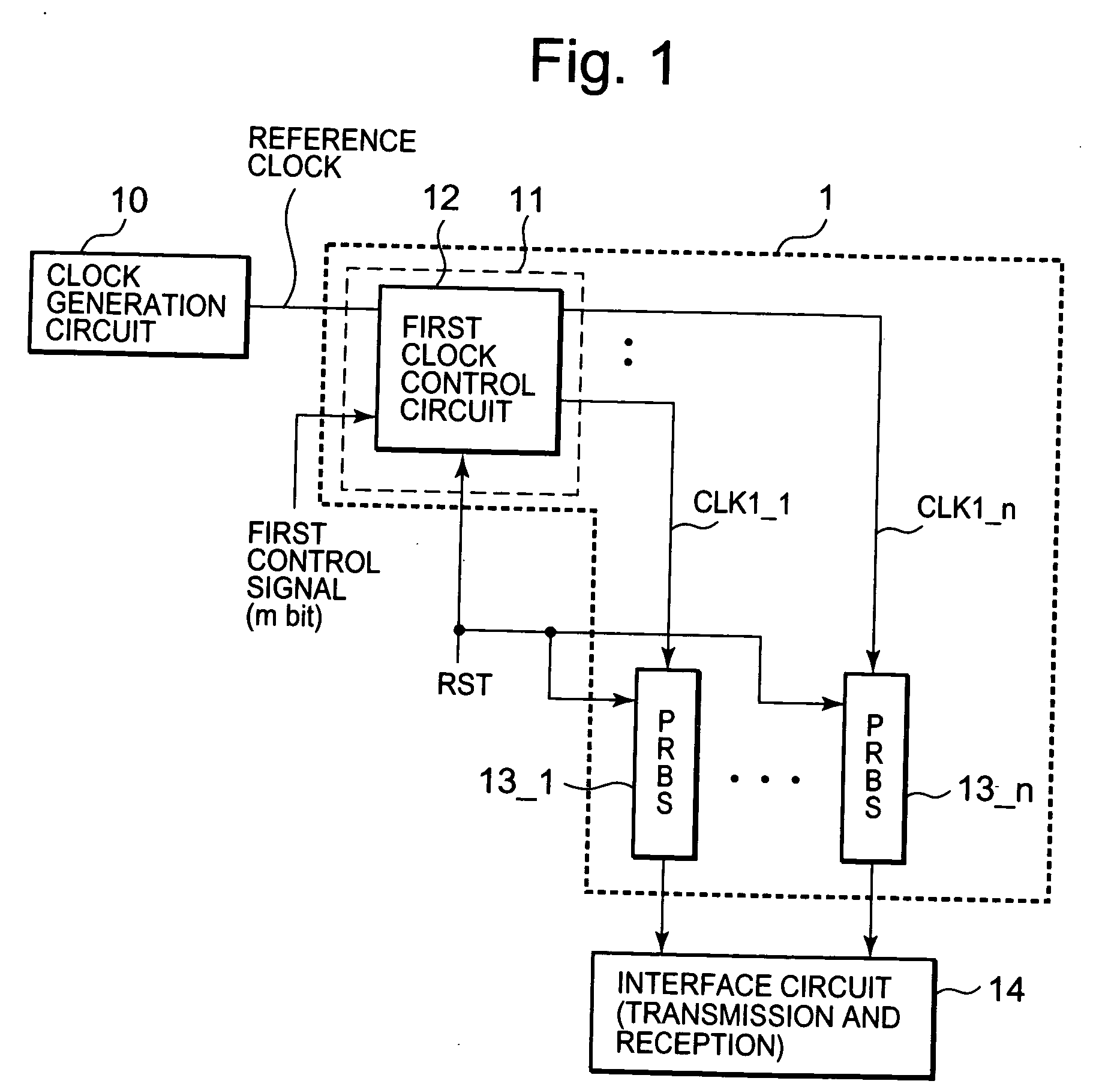
[0033]FIG. 1 shows a block diagram of a test pattern generation circuit 1 according to the present invention. As shown in FIG. 1, the test pattern generation circuit 1 includes a clock control circuit 11 and pseudo random number generation circuits (PRBSs in the drawing) 13_1 to 13_n. The output of each of the pseudo random number generation circuits is connected to a corresponding interface channel. In the following description, n and m each denote an integer. Moreover, a clock generation circuit 10 and an interface circuit 14 are connected to the test pattern generation circuit 1.

[0034]The clock generation circuit 10 outputs reference clocks having certain frequency. This embodiment employs the clock generation circuit 10 configured to output reference clocks after a reset signal RST, which will be described later, changes from a low level to a high level.

[0035]The interface circuit 14 is a circuit to be tested, and is connected to a bus wiring (not illustrated). Moreover, multipl...

embodiment 2

[0057]In the embodiment 1, the descriptions have been provided for the example in which the Seed values (second initial values) of the test patterns, which are used to test the interface circuit 14, are generated by use of the reference clocks, and in which the actual test patterns are generated by use of the reference clocks after the second initial values are generated. However, by additionally preparing test clocks, the actual test patterns can be also generated by use of the test clocks after the second initial values are generated, while the second initial values are generated by use of the reference clocks.

[0058]FIGS. 5 and 6 show an embodiment corresponding to this case. FIG. 5 is a block diagram of a test pattern generation circuit 1′ of Embodiment 2, and FIG. 6 is a block diagram of a first clock control circuit 12′. In Embodiment 2, selectors 31_1 to 31_n are further provided in addition to Embodiment 1 (FIG. 1), and switches between first clock signals CLK1_1 to CLK1_n, w...

embodiment 3

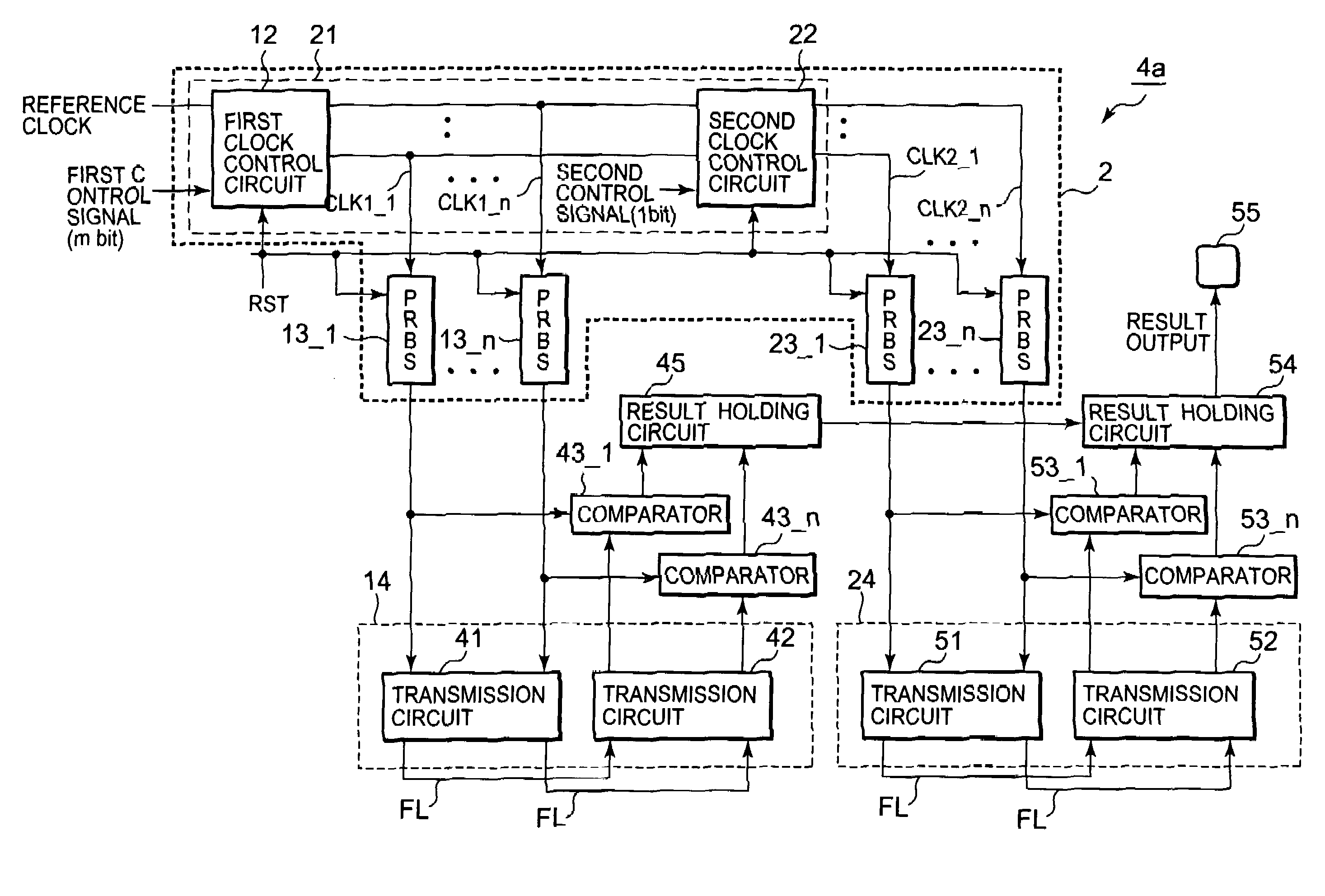
[0068]FIG. 8 shows a block diagram of a test pattern generation circuit 2 according to Embodiment 3. As shown in FIG. 8, in addition to a first clock control circuit 12 (FIG. 2), a clock control circuit 21 of the test pattern generation circuit 2 includes a second clock control circuit 22. Moreover, the test pattern generation circuit 2 includes pseudo random number generation circuits 23_1 to 23_n for the second clock control circuit 22. These pseudo random number generation circuits 23_1 to 23_n are substantially the same as the pseudo random number generation circuits 13_1 to 13_n according to Embodiment 1. In addition, interface circuits 14 and 24 are circuits to be tested, and are connected to bus wirings (not illustrated).

[0069]Here, the second clock control circuit 22 is described in detail. First clock signals CLK1_1 to CLK1_n outputted by the first clock control circuit 12 are inputted to the second clock control circuit 22. Then, the second clock control circuit 22 outputs...


PUM


Abstract

A test pattern generation circuit has multiple pseudo random number generation circuits and a clock control circuit. The pseudo random number generation circuits are provided corresponding to the respective signal lines in a bus wiring, and have predetermined first initial values, which take the same value. In response to first clock signals, the pseudo random number generation circuits generate pseudo random numbers including the first initial values as starting values. According to the value of a control signal, the clock control circuit determines the output-start timings of the first clock signals to be respectively provided to the multiple pseudo random number generation circuits.

Description

BACKGROUND OF THE INVENTION[0001]1. Field of the Invention[0002]A test pattern generation circuit according to the present invention particularly relates to a test pattern generation circuit and for giving pseudo random numbers as test patterns to an interface circuit having a multiple-bit configuration.[0003]2. Description of Related Art[0004]Among malfunctions in a semiconductor device, a malfunction in an interface circuit connected to a bus wiring has been a problem in recent years. The interface circuit connected to the bus wiring transmits and receives random data pieces to and from the bus wiring. A certain order of transmitted / received data pieces may cause interference between the data pieces in the interface circuit, thereby leading to an occurrence of a malfunction in which an error occurs in the transmitted / received data pieces. The interface circuit is required to perform excellent transmission and reception even for various types of data that are likely to cause a malf...

Claims


Application Information

Patent Timeline
IPC IPC(8): G01R31/3183G06F11/263
CPCG01R31/31813G06F1/04
Inventor NAKAMURA, HISASHI
Owner RENESAS ELECTRONICS CORP
Why Eureka
Try Eureka