
Parking brake assembly for railway vehicle brake system

a technology for brake systems and railway vehicles, applied in brake systems, braking components, friction linings, etc., can solve problems such as unusable movement of railway cars, and achieve the effect of safe and convenient operation

Active Publication Date: 2008-07-31
WABTEC HLDG CORP
View PDF2 Cites 34 Cited by
  • Summary
  • Abstract
  • Description
  • Claims
  • Application Information

AI Technical Summary

Benefits of technology

[0010]It is, therefore, one of the primary objects of the present invention to provide a parking brake assembly for a railway vehicle braking system that is capable of maintaining brakes in the applied position upon loss of the air pressure in the brake pipe.
[0014]It is a further object of the present invention to provide a parking brake assembly for a railway vehicle braking system which by virtue of being automatically activated upon the loss of air pressure will eliminate the possibility of operator error in applying the parking brake.
[0015]It is another object of the present invention to provide a parking brake assembly that can be easily retrofitted into currently used braking systems.
[0018]Another object of the present invention is to provide a manual release mechanism for manually releasing spring-applied parking brake assembly that can be safely and conveniently operated without reaching into confines of the brake systems.
[0019]A further object of the present invention is to provide a manual release mechanism for manually releasing a spring-applied parking brake assembly that can temporarily latch the parking brake assembly in the released position.

Problems solved by technology

However, it has been known for an operator to improperly apply the hand brake causing undesirable movement of the railway cars.

Method used


Image

  • Parking brake assembly for railway vehicle brake system
  • Parking brake assembly for railway vehicle brake system
  • Parking brake assembly for railway vehicle brake system

Examples


Embodiment Construction

[0034]Prior to proceeding to the more detailed description of the present invention, it should be noted that, for the sake of clarity and understanding, identical components which have identical functions have been identified with identical reference numerals throughout the several views illustrated in the drawing figures.

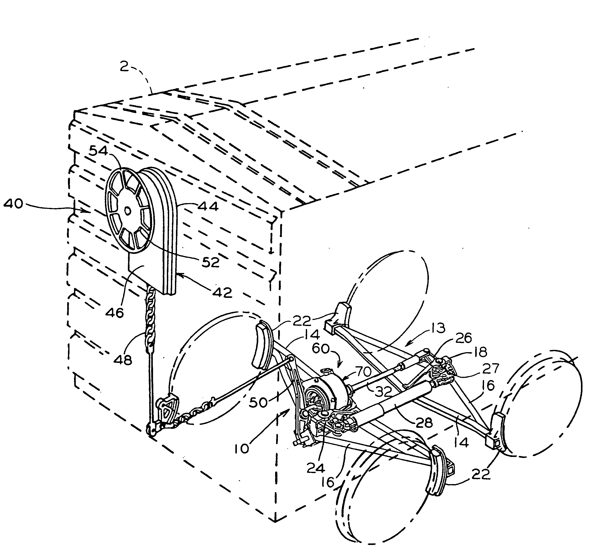
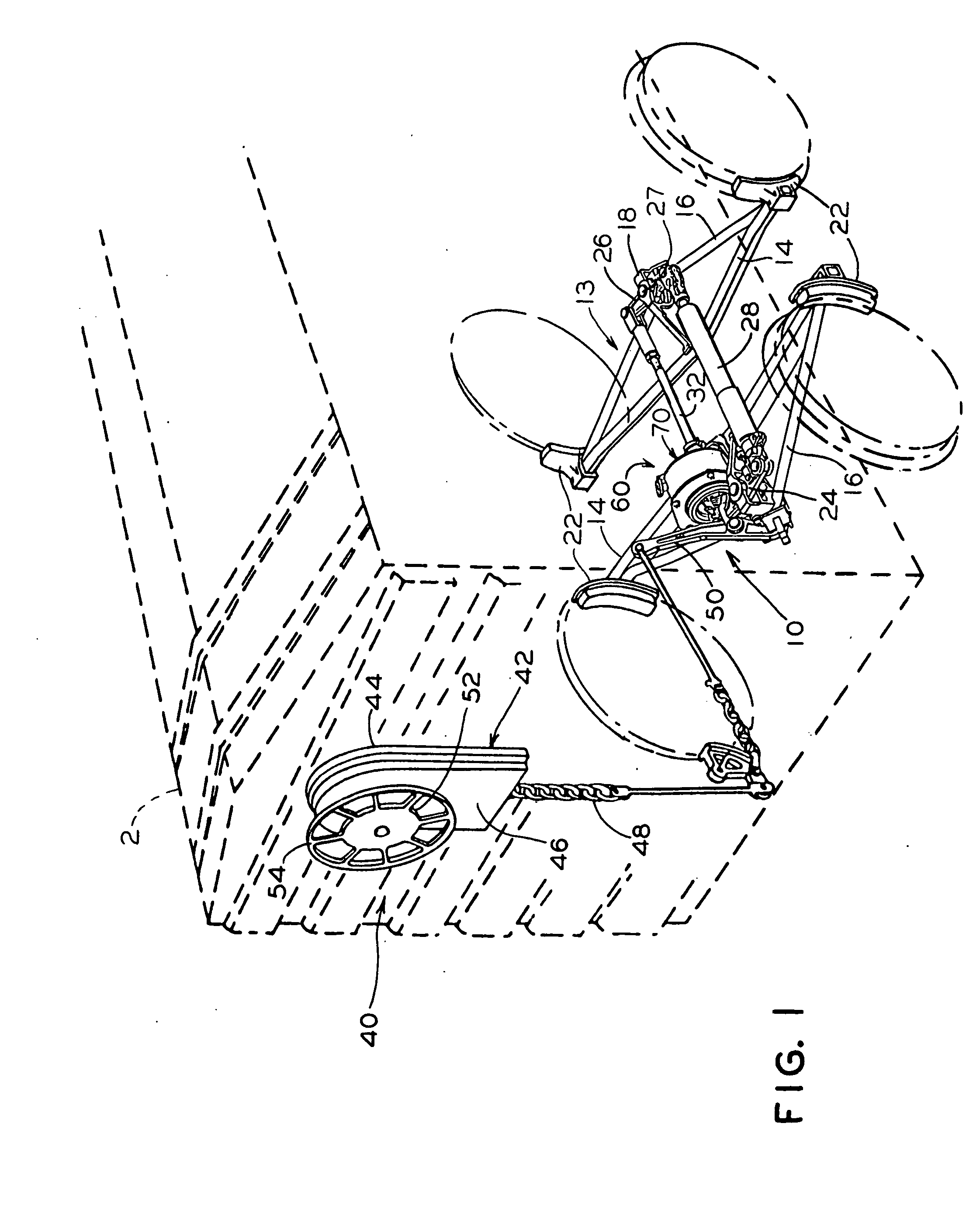
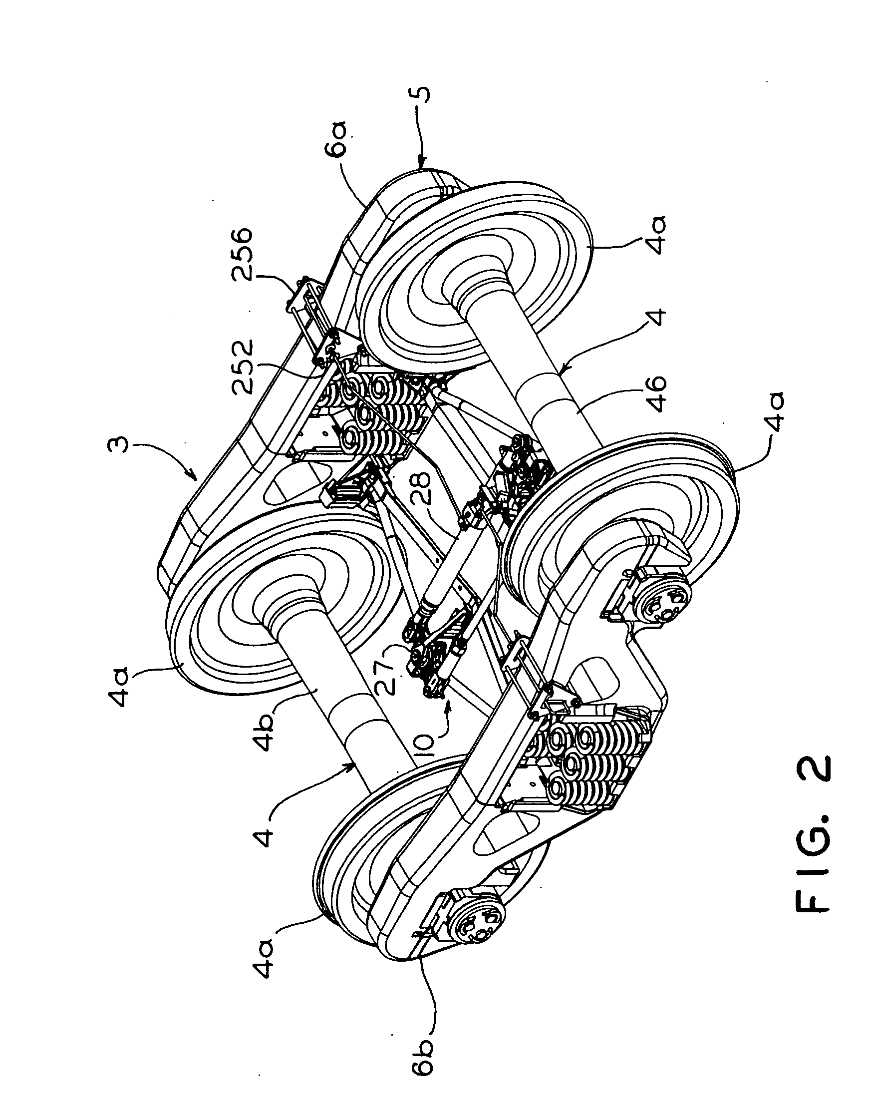
[0035]The best mode for carrying out the invention is presented in terms of its presently preferred embodiment, herein depicted within FIGS. 1 through 12. However, the invention is not limited to the described embodiment, and a person skilled in the art will appreciate that many other embodiments of the invention are possible without deviating from the basic concept of the invention and that any such work around will also fall under scope of this invention. It is envisioned that other styles and configurations of the present invention can be easily incorporated into the teachings of the present invention, and only one particular configuration shall be shown and des...


PUM


Abstract

A parking brake assembly for a railway car includes a ratchet mounted for rotation on a threaded piston rod of a brake actuator and a holding pawl engageable with the ratchet for maintaining a push rod of the parking brake assembly to apply braking force when the air pressure is lost in the brake pipe and releasing the push rod to accordingly release the braking force when the supply of air pressure in the brake pipe is restored. An operating lever and a cylinder connected thereto are provided for selectively rotating the holding pawl. Valve is provided for supplying air pressure to and evacuating it from the cylinder. Release mechanism is provided for manually releasing the braking force. The parking brake assembly is employed with either truck-mounted or carbody-mounted braking system.

Description

CROSS-REFERENCE TO RELATED APPLICATIONS[0001]This application is related to and claims priority from Provisional Patent Application Ser. No. 60 / 898,564 filed on Jan. 31, 2007.FIELD OF THE INVENTION[0002]The present invention relates, in general, to railway vehicle braking systems and, more particularly, this invention relates to a parking brake assembly for use in a railway vehicle braking system and, still more particularly, the present invention relates to a parking brake assembly for use in a railway vehicle truck mounted brake rigging and, yet more specifically, the present invention relates to a release mechanism for use with a railway vehicle parking brake assembly.BACKGROUND OF THE INVENTION[0003]As is generally well known in the railway industry, the brake system used on the railway cars employs a plurality of force transmitting members to convert supply of the pneumatic fluid pressure from the brake pipe into a mechanical force to apply and bias one or more brake shoes agai...

Claims


Application Information

Patent Timeline
Patent Type & Authority Applications(United States)
IPC IPC(8): B61H13/00F16D65/22
CPCB60T13/24B60T17/086B60T15/021
Inventor SOMMERFELD, HOWARDMARLOW, JONATHONMORIARITY, MICHAEL J.KANJO, WAJIHMEYER, DAVIDANDERSON, BRADLEYRING, MICHAEL
Owner WABTEC HLDG CORP
Learn More