
Self-adjusting seat for rotary valve

a self-adjusting, valve technology, applied in the field of valves, can solve the problems of increasing the cost of manufacturing such valves, affecting the sealing capability or service life of the valve, and the extruded section of the seal can become cut or otherwise damaged by the moving valve components

Inactive Publication Date: 2008-07-31
HEMIWEDGE VALVE CORP
View PDF20 Cites 31 Cited by
  • Summary
  • Abstract
  • Description
  • Claims
  • Application Information

AI Technical Summary

Benefits of technology

[0010]A valve seat having two movable parts is provided for valves, especially rotary valves. The seat provides for sealing with flow in the normal or preferred direction and in the non-preferred or reverse direction, at either low or high differential pressu

Problems solved by technology

The requirements for close mechanical tolerances in such valves, in effect limiting the “extrusion gap,” can increase the cost of manufacturing such valves.
If a gap forms between seals when the valve is in the open position, this “extrusion gap” may interfere with the sealing capability or service life of the valve because seals, such as o-rings or molded seals, may be extruded into the gap.
When the valve member is rotated under this condition, an extruded section of the seal can become cut or otherwise damaged by the moving valve components.

Method used


Image

  • Self-adjusting seat for rotary valve
  • Self-adjusting seat for rotary valve
  • Self-adjusting seat for rotary valve

Examples


Embodiment Construction

[0025]The use of balls and plugs as sealing elements in rotary valves is well known. A wedge-shaped sealing element in a rotary valve is less well known; its use in a valve body is described in U.S. Pat. Nos. 4,962,911 and 5,333,834, which are hereby incorporated by reference.

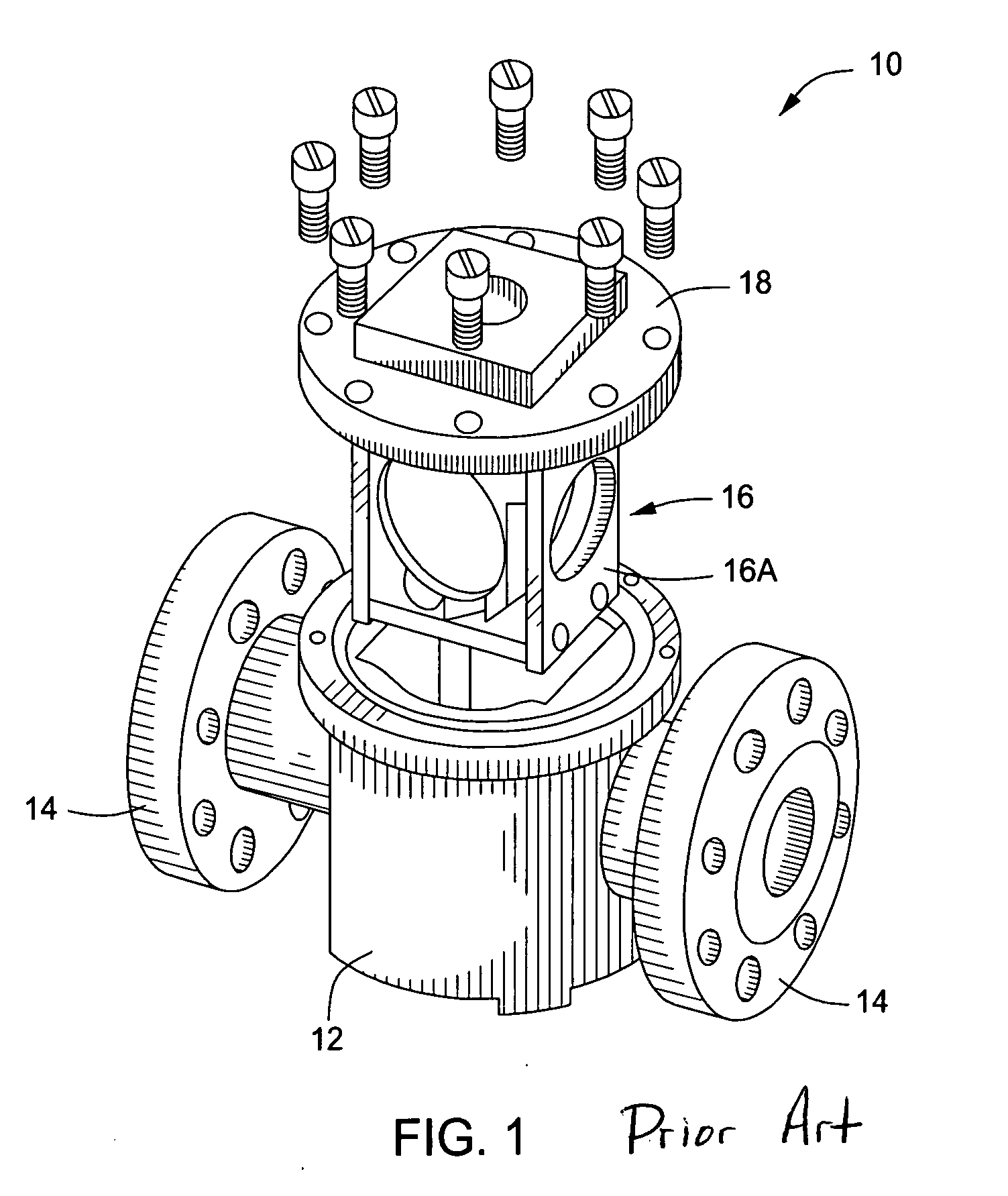
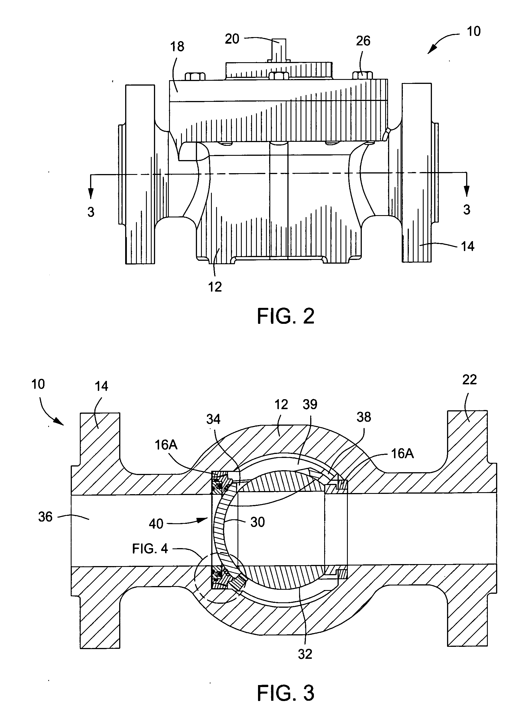
[0026]U.S. Pat. App. Pub. No. US 2006 / 0196544, which is hereby incorporated by reference, discloses a wedge-shaped sealing element, such as disclosed in U.S. Pat. Nos. 4,962,911 and 5,333,834, in a rotary cartridge valve. A cartridge valve is illustrated in FIG. 1. Valve 10 has body 12 and connection flanges 14. Cartridge 16, having plates 16A, may be removed from body 12 by removal of bonnet 18 for replacement of valve elements within the cartridge without disconnecting the flanges of the valve. Valve 10 may be operated by turning a stem (not shown) by about 90 degrees. FIG. 2 illustrates cartridge valve 10 with bonnet 18 and stem 20 in place. The cartridge is adapted to fit in valve body 12 and be easily remo...


PUM


Abstract

A valve seat assembly is provided for rotatable valves. The assembly has concentric rings with a spring to apply force to cause the inner ring to slide within the outer ring. There is a sliding pressure seal between the sliding surfaces. The main seal, adapted to seal against a rotating seal element, is disposed on the outer ring. A second seal, adapted to seal against the wall of the cavity in a valve body, is disposed on the inner ring. A spring may be placed in a groove in the inner or outer ring and selected to provide a force to push apart the main seal and the second seal. The diameter of the sliding seal between the rings is greater than the diameter of the second seal and the diameter of the main seal.

Description

BACKGROUND OF INVENTION[0001]1. Field of the Invention[0002]This invention relates generally to valves having a rotatable valve element such as a wedge or a ball. More particularly, a valve seat assembly is provided, the assembly including provisions for spring-loading and pressure-actuating seals between the rotatable valve element and the valve body when flow in either direction is controlled.[0003]2. Description of Related Art[0004]Rotatable valves such as ball valves have long been well known in the art. Such valves have in common a valve element positioned to rotate in a valve body and a shaft extending from the valve element through a bonnet. Various modifications of ball valves continue, such as described in U.S. Pat. No. 6,378,842, which discloses a ball valve shaft that is rotatably positionably through the bonnet such that the bonnet, the valve shaft and the valve element can be removed from the valve body without removing the valve body from the piping system where it has...

Claims


Application Information

Patent Timeline
IPC IPC(8): F16K25/00
CPCF16K5/0689F16K5/0673
Inventor LLOYD, SAM SUN
Owner HEMIWEDGE VALVE CORP
Features
  • Generate Ideas
  • Intellectual Property
  • Life Sciences
  • Materials
  • Tech Scout
  • Unparalleled Data Quality
  • Higher Quality Content
  • 60% Fewer Hallucinations
Learn More