Earth leakage circuit breaker

a leakage circuit and earth technology, applied in the direction of circuit breakers, circuit breakers for excess current, switches operated by falling current, etc., can solve the problems of raising production costs, wires are vulnerable to adverse affections of external noise, etc., to reduce the influence of external noise propagating through lead wires, reduce product cost, and save space

Active Publication Date: 2008-07-31
FUJI ELECTRIC FA COMPONENTS & SYST CO LTD
View PDF13 Cites 17 Cited by
  • Summary
  • Abstract
  • Description
  • Claims
  • Application Information

AI Technical Summary

Benefits of technology

[0012]In this construction, all the components of the earth leakage detection circuit (an IC), the sensitivity current-switch and the action time switch for setting a sensitivity current and an action time of the earth leakage circuit breaker, and the earth leakage test switch are mounted and arranged in a sheet of circuit board (a printed circuit board), and connected to each other by a conductor pattern formed on the circuit board. As a result, such lead wires as in the conventional structure shown in FIGS. 6 and 7 have become unnecessary that thread their routes through the interior of the main housing to make connections between the board of the earth leakage detection circuit and those switches that are disposed at separate places in the main housing. Therefore, cost reduction in the product has been achieved by virtue of decrease in the number of components related to the wiring and the man-hour for the wiring work, as well as the saving in space. In addition, the influence of external noises propagating through the lead wires is also reduced.
[0013]The circuit board is accommodated in a unit case of the earth leakage trip unit in combination with the trip coil. This construction has simplified installation into the main housing of the circuit breaker and handling of the circuit board and other components, and further, prevented undesired effects of the arc gas and heat generated in the current interruption action, thereby ensuring high reliability.
[0014]The earth leakage trip unit comprises a lower case accommodating the trip coil, an upper case accommodating the circuit board and laid on the lower case, and a cover for the upper case. Terminals of the circuit board, an end of the upper case and an end of the cover are extended to proximity of the zero-phase current transformer. Terminals of the zero-phase current transformer and the terminals of the circuit board are electrically connected, which has shorted the distance between the terminals of the zero-phase current transformer and the terminals of the circuit board, and made the short lead wires be still sufficient for connection wiring between the terminals of the zero-phase current transformer and the terminals of the circuit board.

Problems solved by technology

As a result, the lead wires are vulnerable to adverse affections of external noises, and arc gas and heat generated in the current interruption.
In addition, the wiring work of the lead wires 19 takes a lot of time and may cause troubles, and thus, raises the production costs.

Method used


Image

  • Earth leakage circuit breaker
  • Earth leakage circuit breaker
  • Earth leakage circuit breaker

Examples


Embodiment Construction

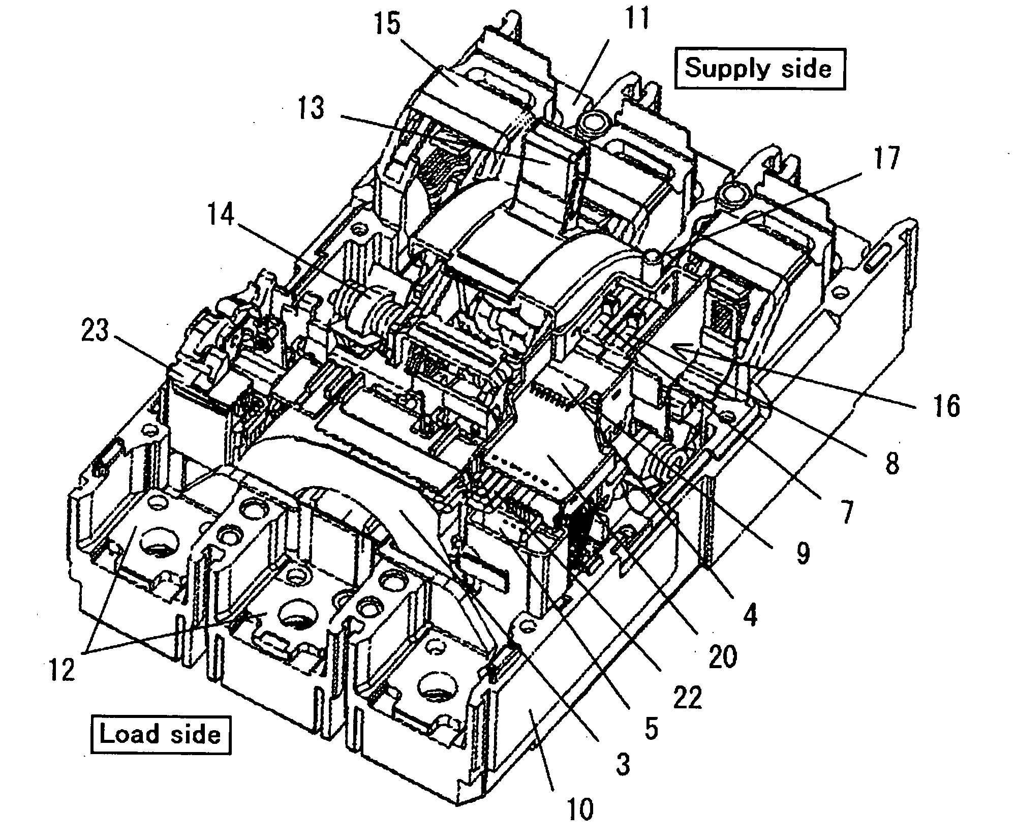
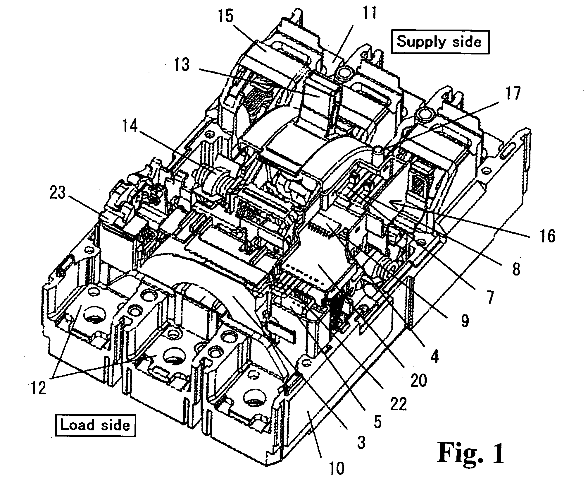
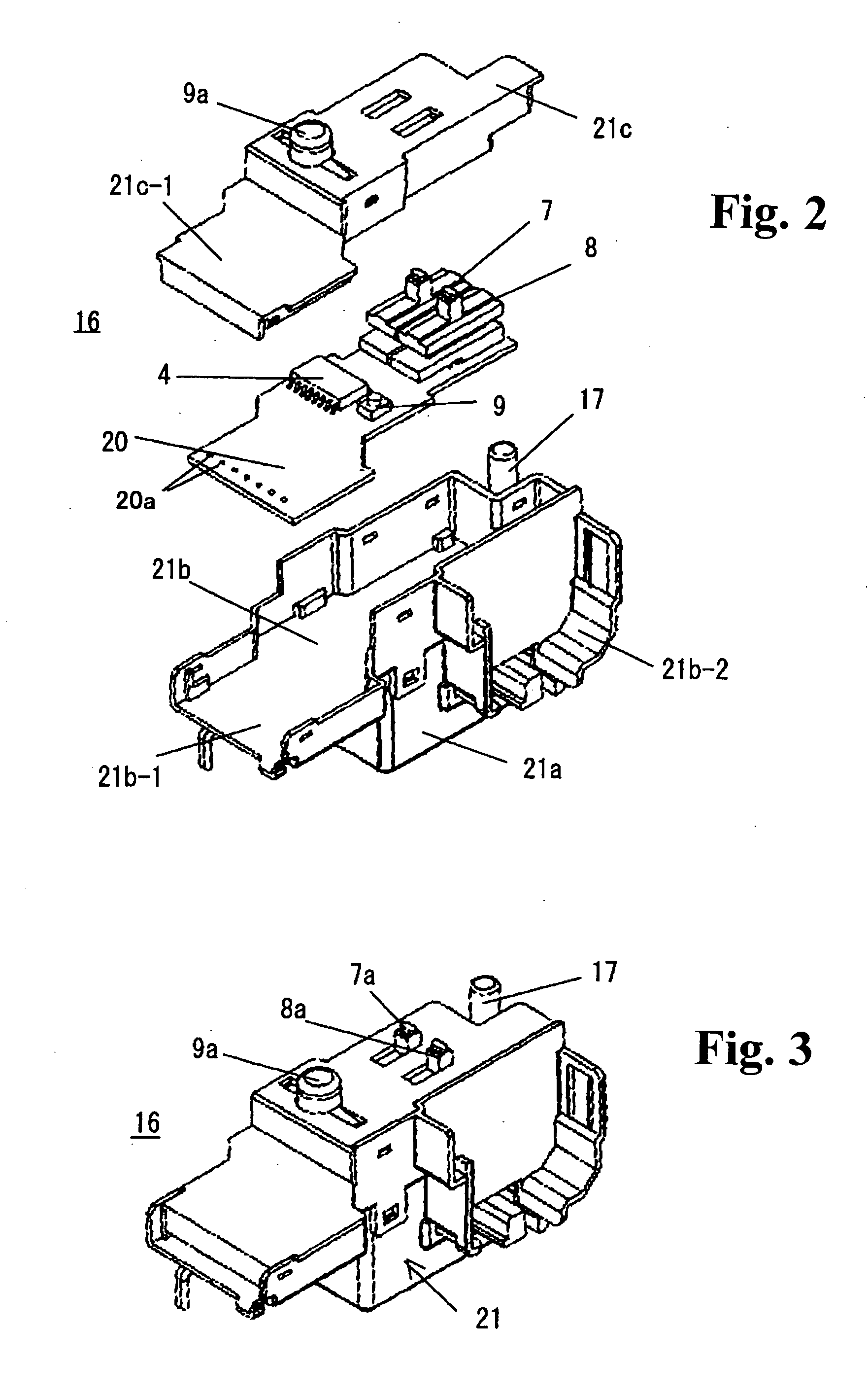
[0022]Now, preferred embodiments will be described with reference to FIGS. 1 through 4. Here, FIG. 1 shows an assembled structure of an earth leakage circuit breaker in which the cover of the main-housing and the cover of the earth leakage trip unit are removed. FIG. 2 is an exploded perspective view of the earth leakage trip unit, FIG. 3 is a perspective view of an assembled earth leakage trip unit shown in FIG. 2, and FIG. 4 is an exploded perspective view of a trip coil installed in the earth leakage trip unit. The same members as in FIG. 6 are given the same symbols and description is omitted.

[0023]The earth leakage circuit breaker of the embodiment shown in FIGS. 1 through 4 is basically similar to the earth leakage circuit breaker of the prior art shown in FIG. 6. In the construction of FIG. 1, however, the earth leakage trip unit 16 that is disposed beside the open-close operation handle 13 and installed in the main housing 10 has the following structure.

[0024]Referring to FI...


PUM


Abstract

A circuit breaker for overcurrent protection and earth leakage protection includes a main housing, a circuit board, a zero-phase current transformer, an earth leakage detection circuit, a trip coil, a sensitivity current-switch, an action time switch, and an earth leakage test switch. The earth leakage detection circuit, the sensitivity current-switch, the action time switch, and the earth leakage test switch are mounted on the circuit board and installed in the main housing.

Description

BACKGROUND OF THE INVENTION AND RELATED ART STATEMENT[0001]Molded case circuit breakers and earth leakage circuit breakers are known as protective devices in a low voltage distribution system. An earth leakage circuit breaker now manufactured in Japan generally has a construction with components for over current protection function and components for ground-fault protection function in a monolithic main housing. In order to improve the ease of use in the user side, an earth leakage circuit breaker has a common external dimension of the main housing shared by a molded case circuit breaker that has the same ampere frame (AF), and installs the functional components mentioned above in the main housing.[0002]FIG. 5 shows a circuit diagram of an earth leakage circuit breaker, and FIGS. 6 and 7 show a construction of a circuit breaker of prior art. In FIG. 5, the reference numeral 1 designates a three-phase main circuit; the reference numeral 2, an open-close contact of the main circuit 1;...

Claims


Application Information

Patent Timeline
Patent Type & Authority Applications(United States)
IPC IPC(8): H01H83/04
CPCH01H71/0207H01H83/226H01H83/04H01H83/06
Inventor NAKANO, MASAAKIASANO, HISANOBU
Owner FUJI ELECTRIC FA COMPONENTS & SYST CO LTD
Why Eureka
Try Eureka