Apparatus and method for providing a supply voltage and a load modulation in a transponder

a technology of supply voltage and load modulation, applied in the direction of electric variable regulation, process and machine control, instruments, etc., can solve problems such as parallel oscillating circuits

Inactive Publication Date: 2008-07-31
INFINEON TECH AG +1
View PDF3 Cites 26 Cited by
  • Summary
  • Abstract
  • Description
  • Claims
  • Application Information

AI Technical Summary

Benefits of technology

[0010]According to embodiments, the present invention provides a device for providing a supply voltage and a load modulation in a transponder with a means having a resistance controllable by a

Problems solved by technology

This results in a paral

Method used


Image

  • Apparatus and method for providing a supply voltage and a load modulation in a transponder
  • Apparatus and method for providing a supply voltage and a load modulation in a transponder
  • Apparatus and method for providing a supply voltage and a load modulation in a transponder

Examples


Embodiment Construction

[0020]With respect to the following description, it is to be noted that, in the various embodiments, equal functional elements or those operating in the same way have the same reference numerals, and thus the descriptions of these functional elements are interchangeable in the various embodiments illustrated in the following.

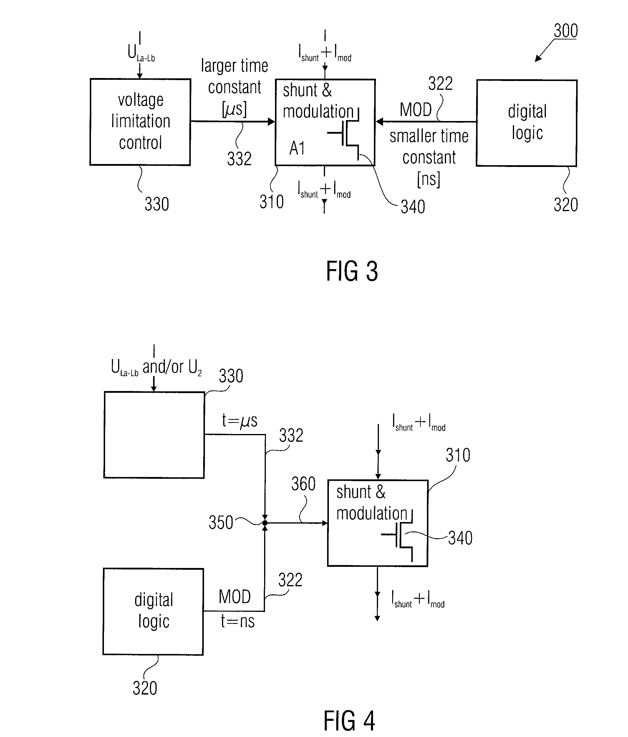
[0021]Before the inventive concept and embodiments of the present invention will be explained in more detail with reference to FIGS. 3 to 7, the functional principle of voltage regulation and load modulation in a transponder will be explained below based on FIGS. 1 and 2.

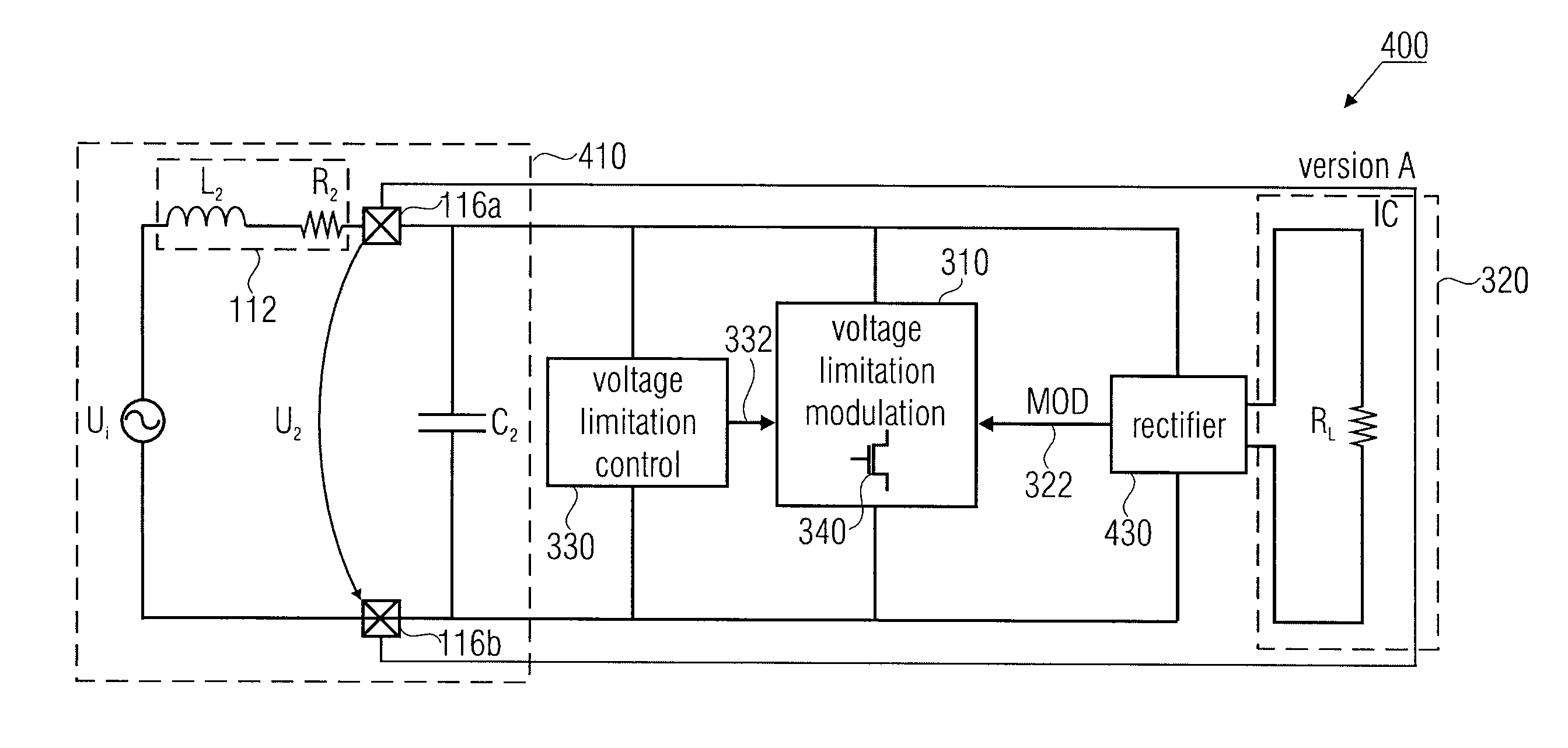
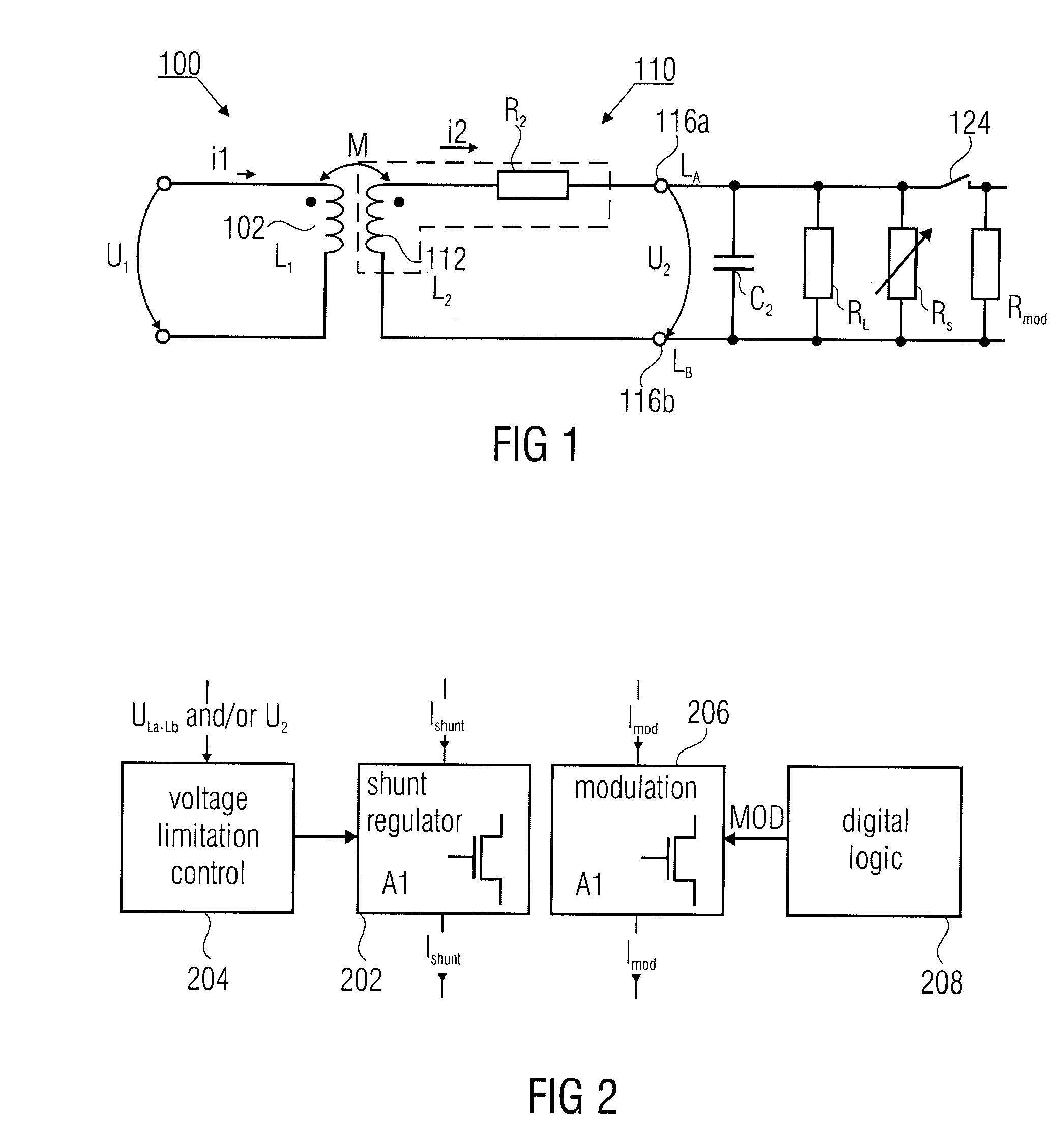
[0022]FIG. 1 shows an equivalent circuit diagram of a magnetic coupling between a reader 100 with a reader coil 102 having an inductance L1 and a transponder 110 with a transmission / reception coil 112 having an inductance L2 and winding resistor R2.

[0023]The inductance L2 of the transponder coil 112 is coupled to a first terminal of the resistor R2 via a first terminal. A second terminal of the ...


PUM


Abstract

A device for providing a supply voltage and a load modulation in a transponder with a unit having a resistance controllable by a control signal at a control input thereof, a unit for applying a load modulation signal to the control input, and a unit for applying a voltage limitation control signal to the control input.

Description

CROSS-REFERENCE TO RELATED APPLICATION[0001]This application claims priority from German Patent Application No. 10 2007 004 843.4, which was filed on Jan. 31, 2007, and is incorporated herein by reference in its entirety.BACKGROUND[0002]The present invention relates to an apparatus and method for providing a supply voltage and a load modulation in a transponder, as it may particularly be used in an RFID transponder (RFID=radio frequency identification).[0003]So-called RFID technology has been used for some time, among other things, in the area of automatic identification of products, persons, goods and animals. RFID technology is a radio-based, contactless identification method which originally used radio frequencies in the radio frequency range (100 kHz to some 10 MHz), wherein, however, there are now used frequencies down to the microwave range. Advantages of these systems, for example as compared to barcode systems, are, among other things, a significantly higher capacitance, rob...

Claims


Application Information

Patent Timeline
IPC IPC(8): H04B1/59
CPCG06K19/0723H04B5/0018H04B5/0031H04B5/0037H04L27/08H04B5/0062H04B5/0081H04L27/04H04B5/0056
Inventor KLAPF, CHRISTIANHOFER, GUENTERKARGL, WALTERMISSONI, ALBERTHOLWEG, GERALD
Owner INFINEON TECH AG
Why Eureka
Try Eureka