Direction indicator system, and electric wheelchair, walking stick, and game controller utilizing said direction indicator system

a direction indicator and indicator system technology, applied in navigation instruments, mechanical pattern conversion, gearworks, etc., can solve problems such as dangerous devices, complicated components around movable pegs, and thin movable pegs, and achieve the effect of stimulating the tactual sensation of users

Inactive Publication Date: 2008-07-31
FUJITSU COMPONENENT LTD
View PDF17 Cites 20 Cited by
  • Summary
  • Abstract
  • Description
  • Claims
  • Application Information

AI Technical Summary

Benefits of technology

[0011]According to an aspect of the present invention, there is provided a direction indicator system including: an electromagnetic drive actuator that has a moving part that can slide back and forth, side to side, and diagonally; and a drive controlling unit that controls a sliding direction of the moving part, based on direction indicating information that is supplied from the outside. In accordance with this invention, the drive controlling unit controls the sliding action of the moving part of the electromagnetic drive actuator, based on the direction indicating information supplied from the outside. Accordingly, the moving part can stimulate the tactual sensation of the user at his / her finger, hand, or elbow at a certain distance. In this manner, a direction can be presented by stimulating the tactual sense of the user, instead of the visual or auditory sense. Thus, even if the user is a visually impaired person or a hearing-impaired person, the user can be certainly informed of a desired direction.

Problems solved by technology

Since a driving mechanism and a logic circuit for selectively moving the movable pegs up and down in accordance with position information are required, the components around the movable pegs become complicated.
However, the movable pegs are thin, needle-like structures.
If the movable pegs are pushed up by strong force, the device becomes dangerous.
On the other hand, if the movable pegs are pushed by weak force, the user might not recognize the stimulation of the tactual sensation.
However, it is difficult for this tactual direction indicating device alone to certainly inform the user of the traveling direction.
Therefore, if the user is a visually impaired person or a hearing-impaired person, it is difficult to utilize the technique disclosed in Japanese Unexamined Patent Publication No. 2000-352521.

Method used


Image

  • Direction indicator system, and electric wheelchair, walking stick, and game controller utilizing said direction indicator system
  • Direction indicator system, and electric wheelchair, walking stick, and game controller utilizing said direction indicator system
  • Direction indicator system, and electric wheelchair, walking stick, and game controller utilizing said direction indicator system

Examples


first embodiment

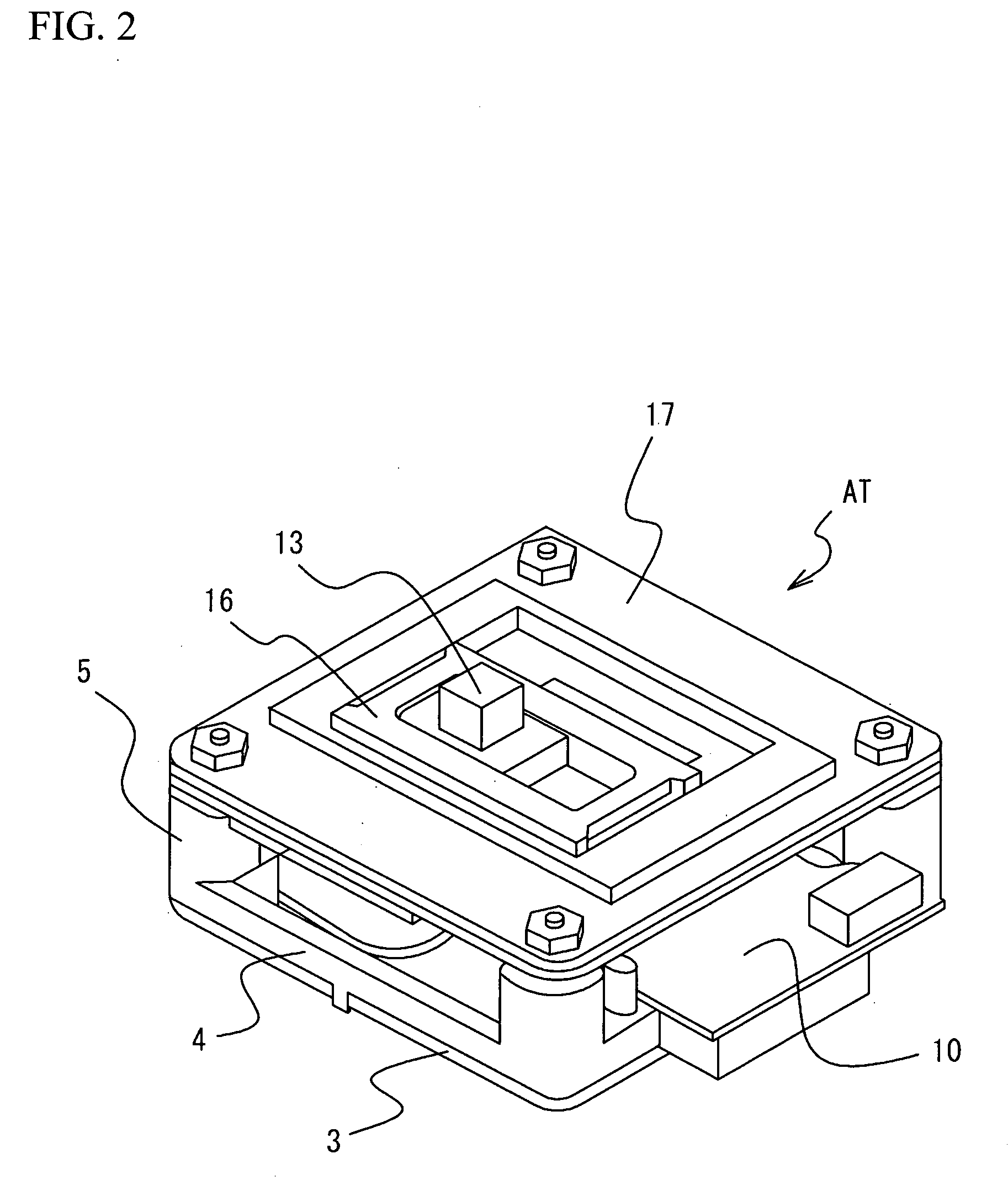
[0046]FIG. 4 illustrates an electric wheelchair MW in accordance with a first embodiment that employs the actuator AT. The actuator AT is used as the operation unit WR of the electric wheelchair MW. In FIG. 4, the operation unit WR is shown in an enlarged view in an ellipse. The operation unit WR has a stick-like shape. For example, the operation unit WR is tilted in a desired direction, the electric wheelchair MW can be moved. The actuator AT is embedded in the upper end portion of the operation unit WR. When an operator grabs the operation unit WR, his / her thumb should touch the key top 13 of the actuator AT. Accordingly, when the key top 13 slides in a predetermined direction, the operator can sense the movement through stimulation of the tactual sensation.

[0047]FIG. 5 is a block diagram showing the structure for controlling the actuator AT that indicates the traveling direction of the electric wheelchair MW. The electric wheelchair MW includes a position information processor PF...

second embodiment

[0063]A second embodiment of the present invention is now described. In the second embodiment, the same structure as the structure employed in the electric wheelchair MW of the first embodiment is employed in a walking stick. In the following description of the second embodiment, the same components as those of the first embodiment are denoted by the same reference numerals as those used in the first embodiment, and explanation of them is omitted here. FIG. 13 shows a white stick WS for a visually-impaired person in accordance with the second embodiment. This white stick WS has the function of indicating a direction. Like the electric wheelchair MW of the first embodiment, the white stick WS has a navigation function, and stimulates the tactual sensation of a visually-impaired person at his / her hand through a sliding action of the actuator AT, so as to inform the person of the traveling direction or the like. More specifically, the actuator AT is set at the top end of a gripping par...

first modification

(First Modification)

[0065]The following is a description of a modification of the second embodiment. FIG. 15 shows a first modification of the second embodiment in which the actuator AT is placed at a side of the gripping part GP. As shown in FIG. 15, the actuator AT is placed on the opposite side from the concave portions CS to be gripped by the user. With this arrangement, the tactual sensation is stimulated at a thumb or a palm of the user. In a case where the actuator AT is placed vertically as in this modification, it is necessary to determine in advance that the top represents the forward direction and the bottom represents the backward direction, for example.


PUM


Abstract

A direction indicator system includes: an electromagnetic drive actuator that has a moving part that can slide back and forth, side to side, and diagonally; and a drive controlling unit that controls the sliding direction of the moving part, based on direction indicating information that is supplied from the outside.

Description

BACKGROUND OF THE INVENTION[0001]1. Field of the Invention[0002]The present invention generally relates to a direction indicator system that indicates a direction with the use of an actuator, and more particularly, to a direction indicator-system-that is incorporated into various structures, and precisely presents a direction to a user (or an operator) by stimulating the tactual sensation of the user. The present invention also relates to devices such as an electric wheelchair that utilizes the direction indicator system.[0003]2. Description of the Related Art[0004]For example, Japanese Unexamined Patent Publication No. 2000-352521 discloses a system for assisting users who use a navigation device. More specifically, Japanese Unexamined Patent Publication No. 2000-352521 discloses a navigation assistance system that shows a direction to a user through a sensory direction indicating device. A tactual direction indicating device in this system determines the tactual cueing necessary f...

Claims


Application Information

Patent Timeline
Patent Type & Authority Applications(United States)
IPC IPC(8): G08B21/00A61F9/08A61F11/04A61H3/06A63F13/213A63F13/215A63F13/216A63F13/28B60R21/00G01C21/00G01C21/26G01C21/36G06F3/01
CPCA61H3/068A63F2300/1043A63F13/06A61H2003/063A63F2300/1037A63F13/24A63F13/285A61H3/061
Inventor KANEKO, MASAHIROSAKURAI, SATOSHIYATSU, NOBUOUCHIYAMA, TAKUYASEGAWA, YURIKO
Owner FUJITSU COMPONENENT LTD
Why Eureka
Try Eureka