
Control System for an Aircraft

a control system and aircraft technology, applied in the field of aircraft control systems, can solve the problems of unnatural and uncomfortable operating arrangement of the operator of the rc aircraft, unfavorable safety and safety of passengers, and difficult to hold for long periods of time, and achieve the effects of reducing fatigue and strain on the arm, simple operation, and reducing the risk of injury

Active Publication Date: 2008-07-31
SCHERER PATRICK L
View PDF25 Cites 21 Cited by
  • Summary
  • Abstract
  • Description
  • Claims
  • Application Information

AI Technical Summary

Benefits of technology

[0011]By disposing the transmitter in the auxiliary unit separate from the main unit, the arm of the operator need not support this weight. Therefore, fatigue and strain to the arm are kept to a minimum, allowing a more comfortable experience which may be sustained for a longer period of time.
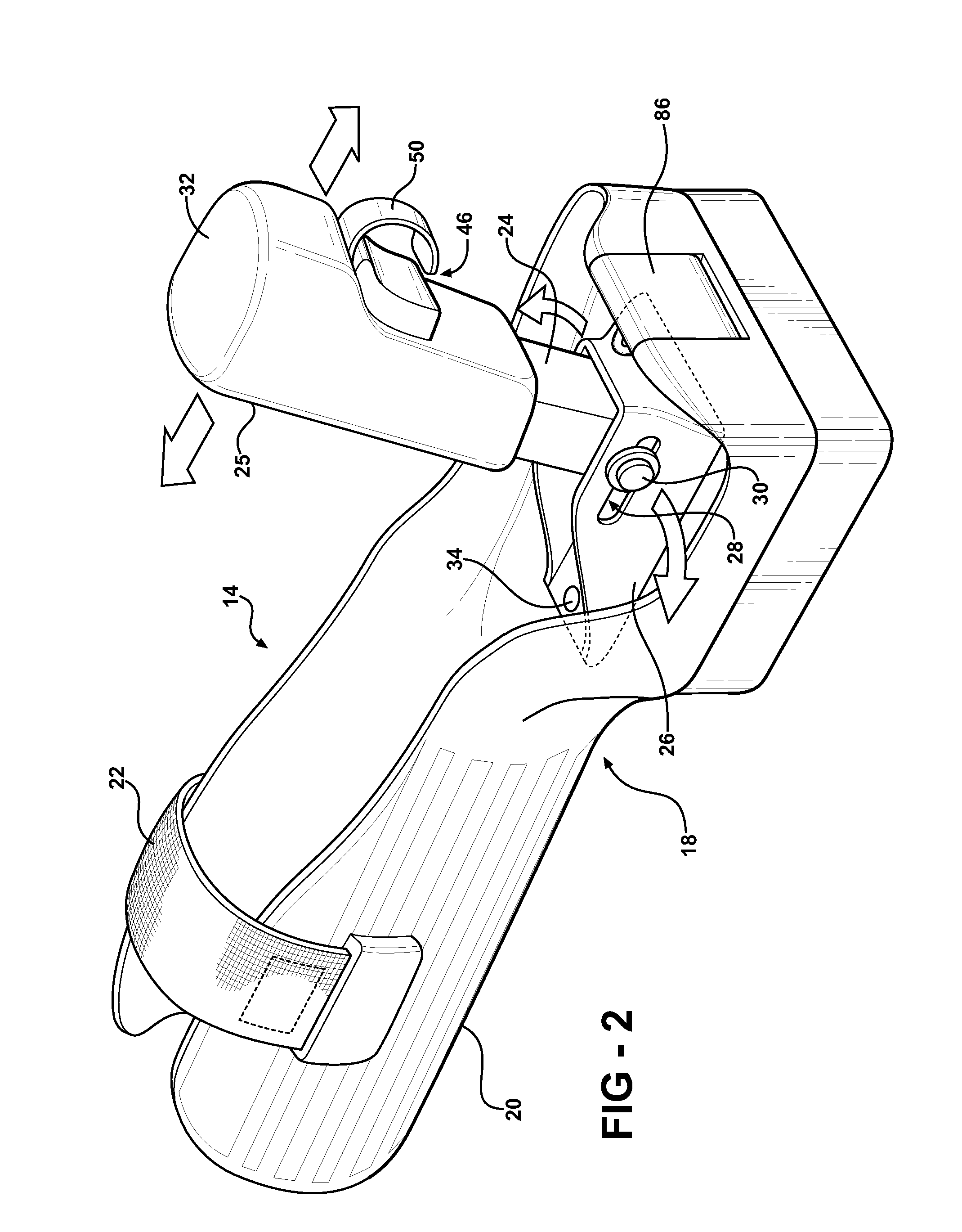
[0012]The control system of the subject invention may also provide a guide piece supported by the structural element and defining an elongated slot. The control stick includes an upper end and a lower end. A pin is disposed in the control stick between the upper and lower ends and defines a first pivot axis. The pin is also slidably disposed in the elongated slot such that the control stick pivots about the pivot axis and simultaneously slides along the elongated slot within a vertical plane. The interface between the control stick and the elongated slot allows for easy movement of the control stick in the vertical plane with a simple, slight movement of the wrist.

Problems solved by technology

First, the weight of the battery and transmitter may tend to make the unit very heavy and difficult to hold for long periods of time.
As a result, neck fatigue often occurs when operating for more than a short-period of time.
This results in an unnatural and uncomfortable operating arrangement for the operator of the RC aircraft.
Moreover, this operating arrangement bears little resemblance to the controls of a cockpit-flown aircraft.
The weight of these components undoubtedly causes arm strain and an uncomfortable operating arrangement.

Method used


Image

  • Control System for an Aircraft
  • Control System for an Aircraft
  • Control System for an Aircraft

Examples


Embodiment Construction

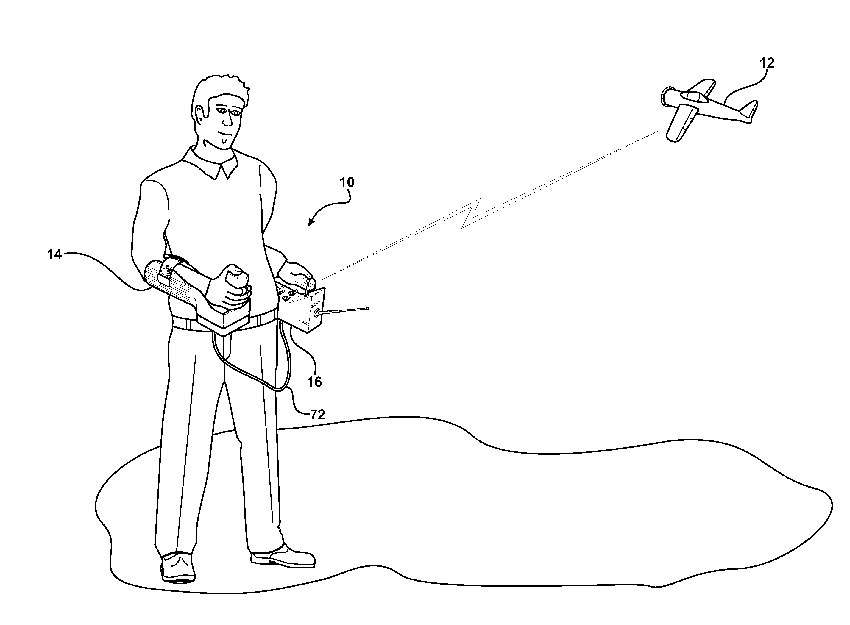
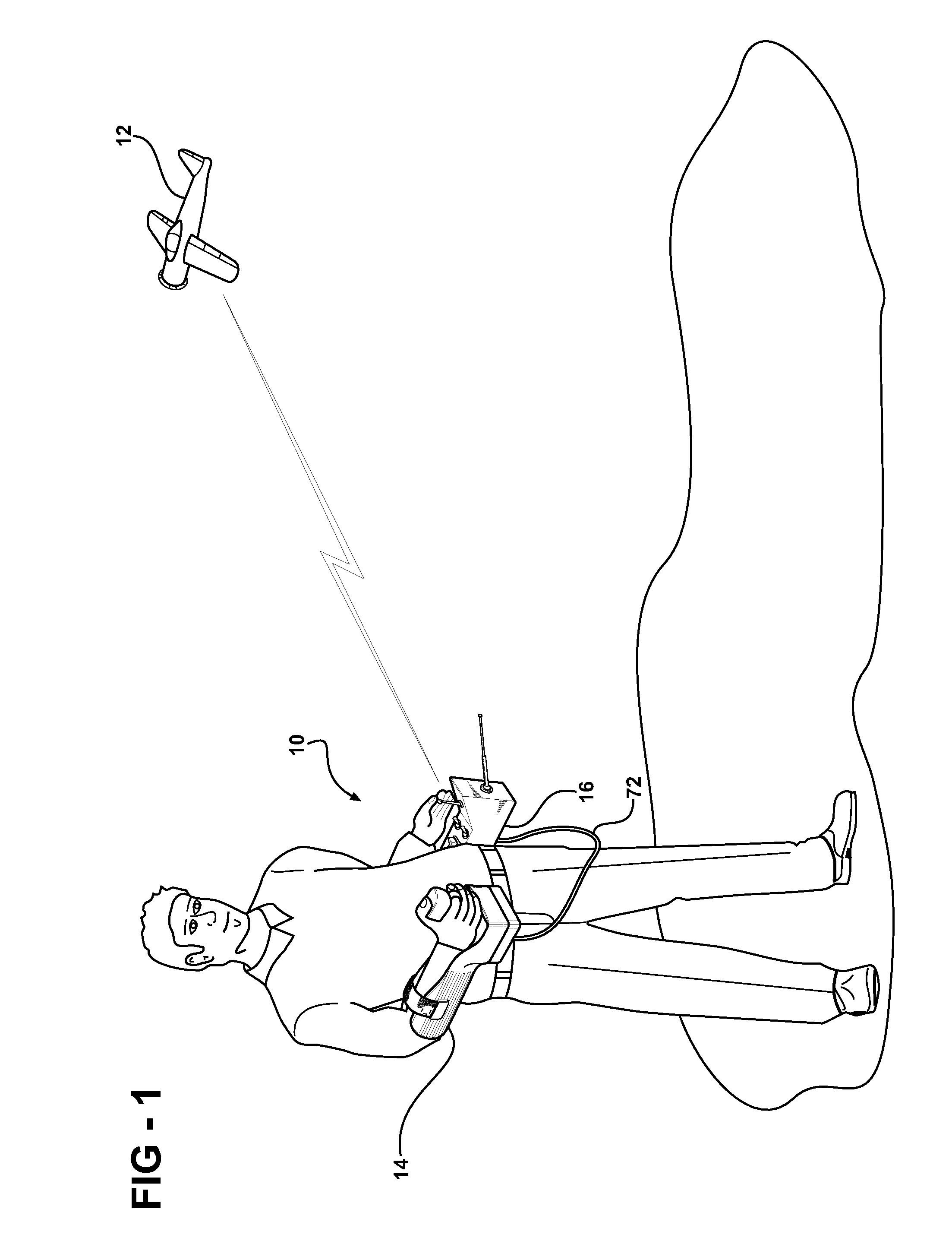
[0025]Referring to the Figures, wherein like numerals indicate corresponding parts throughout the several views, a control system 10 for an aircraft 12 is shown in FIG. 1. The aircraft 12 may be a scale model aircraft 12, such as those operated by hobbyists. However, the control system 10 described herein may be used to control other aircraft 12, such as drone aircraft 12. Furthermore, although FIG. 1 illustrates a fixed wing aircraft 12, those skilled in the art realize that the control system 10 may be used to control rotorcraft, such as helicopters. Moreover, the control system 10 described herein may be used to control other vehicles besides aircraft 12, such as, but not limited to, watercraft, land vehicles (race cars, tanks, etc.), or other remotely controllable objects.

[0026]The control system 10 includes a main unit 14 and an auxiliary unit 16. In a preferred embodiment, the units 14, 16 are physically separate from one another. Although physically separate, the units 14, 16...


PUM


Abstract

A control system for an aircraft includes a main unit and a separate auxiliary unit in communication with the main unit. The main unit includes an arm support allowing attachment to an arm of an operator. The main unit also includes a control stick supported by the structural element and movable in a plurality of directions. The main unit further includes sensors for sensing movement of the control stick. The auxiliary unit includes a transmitter for sending a transmitter signal encoding the movement of the control stick to the aircraft.

Description

CROSS REFERENCE TO RELATED APPLICATION[0001]This application claims the benefit of U.S. Provisional Patent Application Ser. No. 60 / 887,403 filed Jan. 31, 2007.BACKGROUND OF THE INVENTION[0002]1. Field of the Invention[0003]The subject invention relates to a system to control an aircraft, such as a radio-controlled (RC) aircraft.[0004]2. Description of the Related Art[0005]Flying RC aircraft is a popular and growing hobby enjoyed by a wide variety of people. RC aircraft are also used by scientific and government organizations in scientific experiments, such as gathering meteorological information, and military applications, such as drones or spy planes. Flying RC aircraft commonly requires a large, obstruction free area to allow take-offs, landings, and flight of the aircraft.[0006]Typically, most hobbyists control their RC aircraft using a remote control unit. Such units are available from a variety of manufacturers. One example of such a unit may be appreciated from U.S. Design Pat...

Claims


Application Information

Patent Timeline
IPC IPC(8): H03J9/02
CPCA63H30/04
Inventor SCHERER, PATRICK L.
Owner SCHERER PATRICK L
Learn More