
Pipe bursting and replacement apparatus and method

a technology of pipe bursting and pipe replacement, which is applied in the direction of pipe elements, drilling machines and methods, earthwork drilling and mining, etc., can solve the problems of pipe failure, operator's fusing equipment on site, and the failure of expanding taper pullers in systems and applications, so as to limit the magnitude of load and ensure the tensile strength of the pip

Inactive Publication Date: 2008-07-31
EARTH TOOL L L C
View PDF3 Cites 16 Cited by
  • Summary
  • Abstract
  • Description
  • Claims
  • Application Information

AI Technical Summary

Benefits of technology

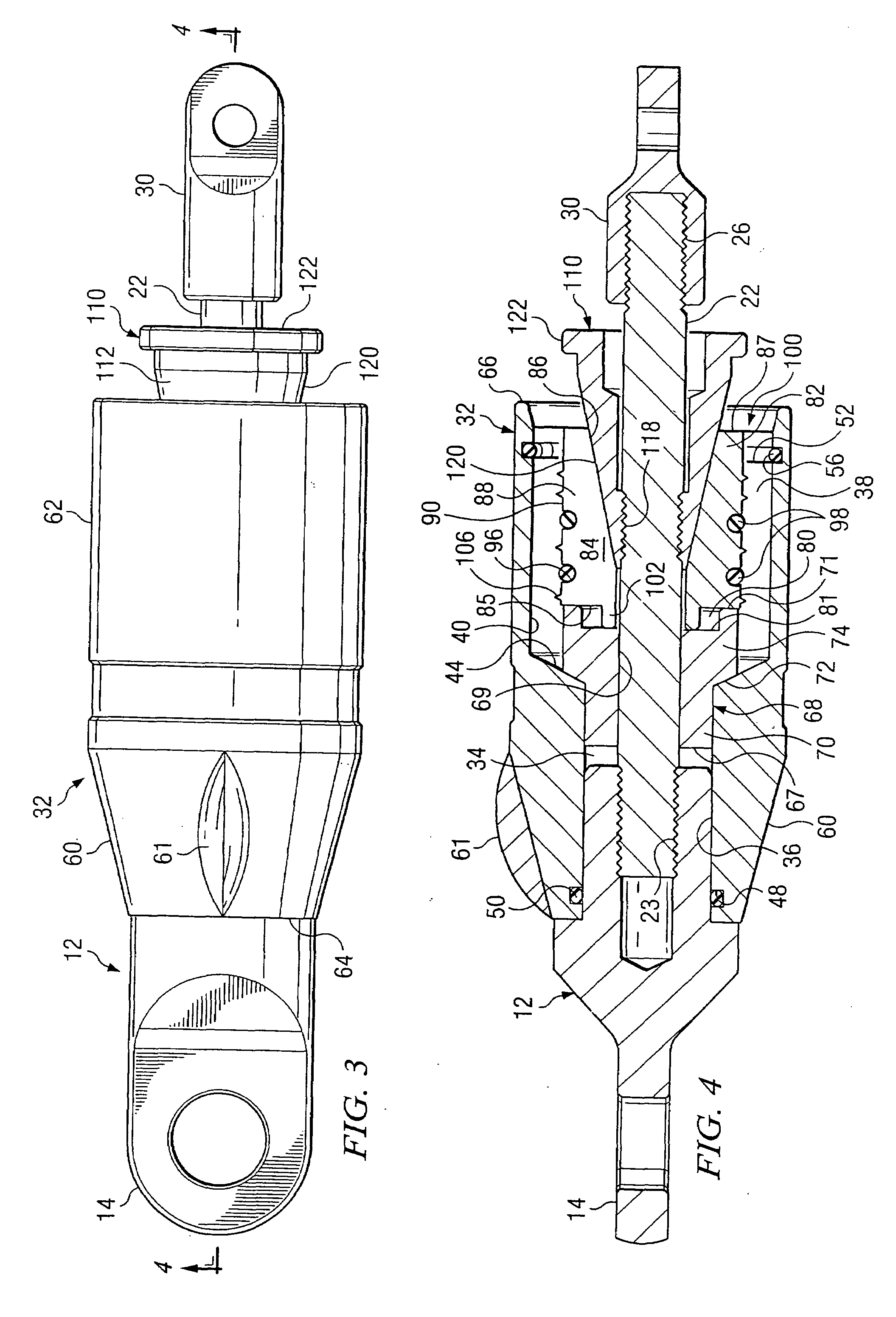
[0010]The invention provides a unitary pipe bursting and pulling tool including a tapered cone pipe puller that limits the magnitude of the load applied to toothed pipe gripping jaws irrespective of the total load placed on the tool. A tapered cone pipe pulling system of the invention limits the axial displacement of the cone to allow the jaws a limited amount of radial displacement. Thus, a replacement pipe may be clamped onto the tool with the deformation of the pipe due to the clamping being limited such that the tensile strength of the pipe is not compromised. In one embodiment, the axial displacement of the cone is limited so that teeth of the pipe gripping jaws penetrate the wall of the replacement pipe to a depth of no more than about 35%, preferably from between 5% and 30%, of the thickness of the replacement pipe wall.

Problems solved by technology

A drawback of existing tapered puller systems is that the load applied by the pulling process typically draws the cone even deeper into the jaws, forcing the jaws deeper into the pliable wall of the plastic pipe.
This extrusion and thinning process can result in the pipe failing before the loading on the pipe exceeds the maximum tensile strength of the pipe.
Thus, expanding taper pullers have not been successfully used in systems and applications where the force of the bursting operation is transferred to the pipe gripping jaws.
While this system apparently works, it has the disadvantage of requiring the operator to have fusing equipment on site during attachment of the pipe to the head.
The fusing process is time consuming, includes the potential of a bad fuse joint, and requires expensive equipment.

Method used


Image

  • Pipe bursting and replacement apparatus and method
  • Pipe bursting and replacement apparatus and method
  • Pipe bursting and replacement apparatus and method

Examples


Embodiment Construction

[0022]While the making and using of various embodiments of the present invention are discussed in detail below, it should be appreciated that the present invention provides many applicable inventive concepts which can be embodied in a wide variety of specific contexts. The specific embodiments discussed herein are merely illustrative of specific ways to make and use the invention and are not to delimit the scope of the invention. References to “tapered” or “conical” shapes or surfaces shall be understood to include not only those exact shapes but also similar shapes approximating those shapes. References to “bursting” will be understood to include both shattering of a frangible pipe and slitting of a ductile pipe, the method of the invention being useful for both of these purposes.

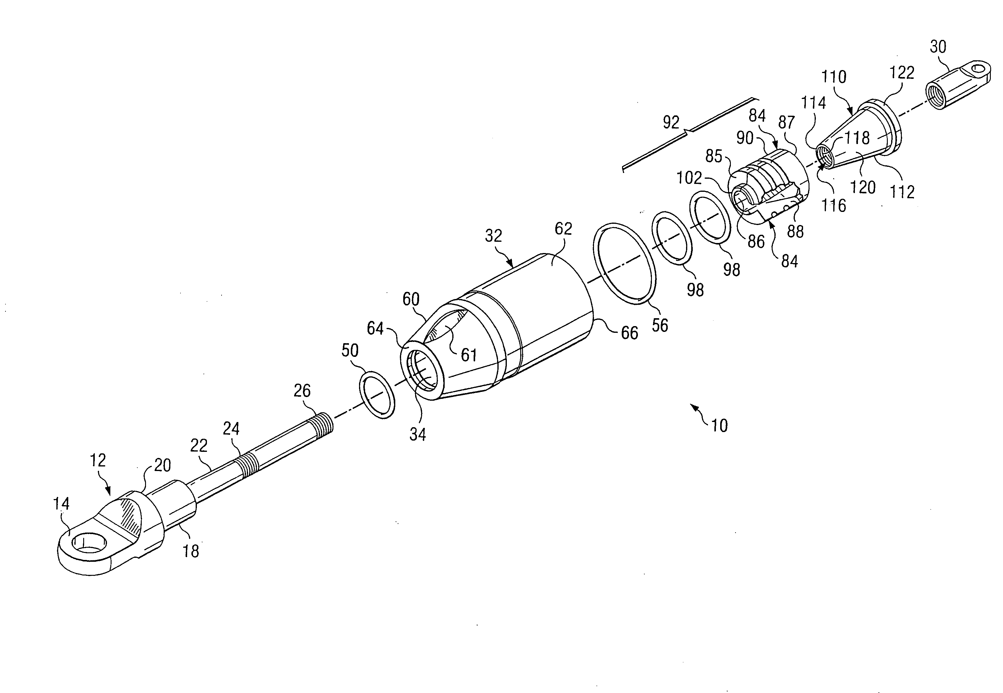
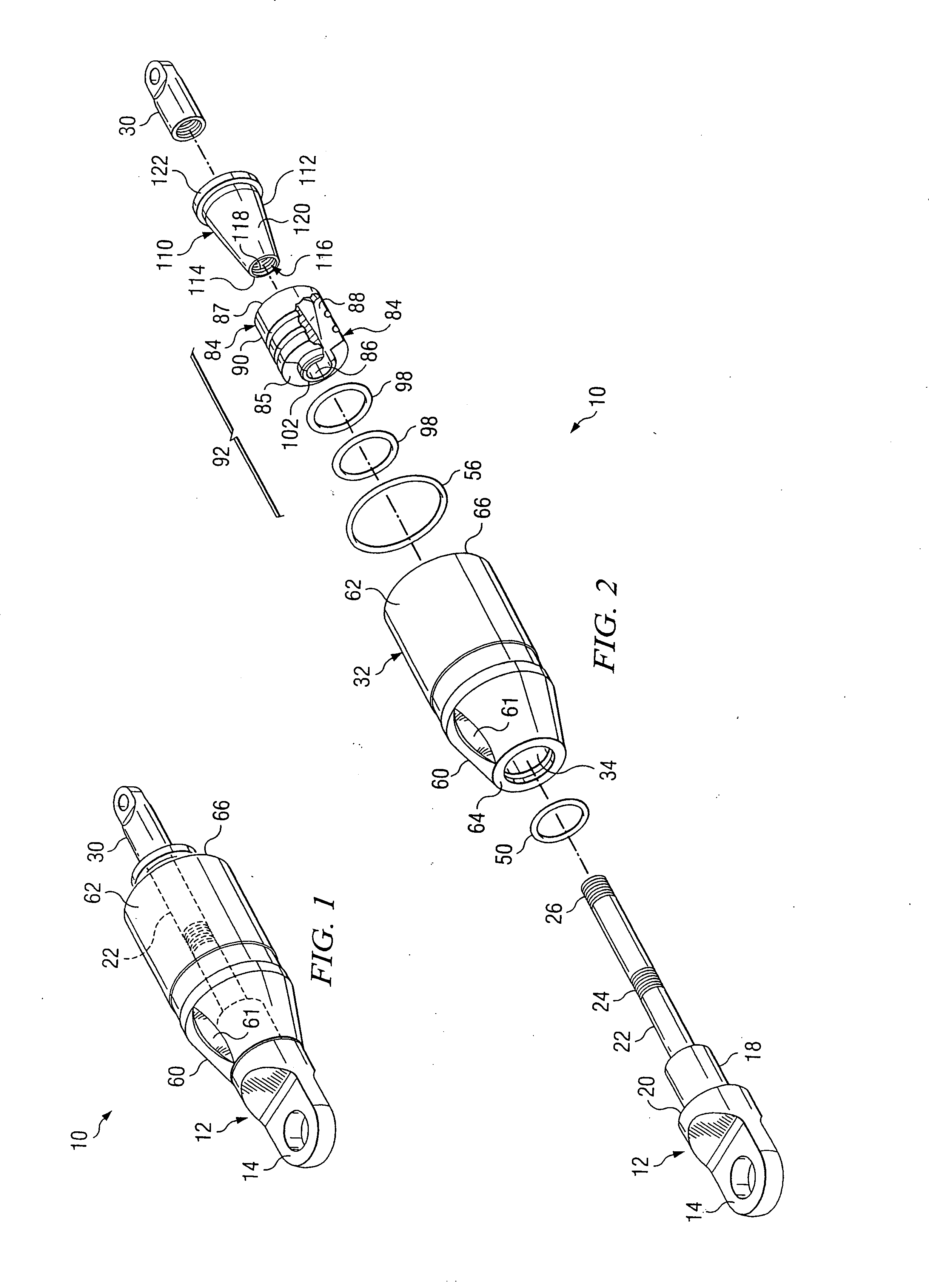
[0023]Referring now to FIGS. 1 through 4, in a first embodiment, a unitary pipe bursting and pulling apparatus 10 according to the invention is designed to be pulled though a horizontal under ground pipe, ...


PUM


Abstract

A pipe bursting and pulling apparatus for use in replacing horizontal underground pipes including a cylindrical body with a tapered forward section including means for attaching one of a cable, rod, rope or chain, the cylindrical body including an annular inner wall defining a longitudinally extending, rearwardly opening recess, a shaft passing through the recess, a plurality of gripping jaws, at least one of the jaws including a pipe gripping tooth extending radially outward relative to a longitudinal axis of the shaft, a tapered expander connected to the shaft and configured to fit between the jaws, the expander forcing the jaws outward to clamp a replacement pipe inserted into the cylindrical body between the jaws and the inner wall when pulled by the shaft, a stop, the stop limiting the forward travel of the expander and preventing outward radial travel of the jaws after the tooth has been engaged in the wall of the replacement pipe whereby the tooth penetrates to a depth of no more than 35% of the thickness of the wall of the replacement pipe.

Description

[0001]This application is a continuation of U.S. patent application Ser. No. 10 / 837,098, filed Apr. 30, 2004, pending which claims priority of U.S. Provisional Patent Application Ser. No. 60 / 467,829, filed May 2, 2003.TECHNICAL FIELD[0002]The invention relates to replacing horizontal underground pipes and in particular to an improved apparatus and method for simultaneously bursting and expanding an existing pipe while simultaneously pulling a replacement pipe through the bore with a unitary tool.BACKGROUND OF THE INVENTION[0003]Existing techniques for replacing existing underground horizontal pipe include a method in which a bursting or slitting tool is pulled through the pipe with a cable, rope, chain or similar pulling means. As the tool is pulled through the pipe, it bursts and expands the bore, readying the bore for a replacement pipe. In one variation, the replacement pipe is pulled through the bore in a separate operation using a pulling apparatus connected to the end of the r...

Claims


Application Information

Patent Timeline
IPC IPC(8): F16L55/18F16L55/165
CPCF16L55/1658E21B7/30
Inventor WENTWORTH, STEVEN W.CRANE, ROBERT F.
Owner EARTH TOOL L L C
Learn More