Radio frequency management system

a technology of radio frequency management and control system, applied in the field of radio frequency technology, can solve the problems of trouble, affecting management integrity, and poor effect of radio frequency identification applications, and achieve the effect of facilitating shop inventory control and eliminating interference among the reading units

Inactive Publication Date: 2008-07-31
J LINK TECH CORP
View PDF3 Cites 2 Cited by
  • Summary
  • Abstract
  • Description
  • Claims
  • Application Information

AI Technical Summary

Benefits of technology

[0007]The present invention has been accomplished under the circumstances in view. It is the main object of the present invention to provide a radio frequency management device which is practical for real-time shop inventory control. To facilitate shop inventory control, every product in the product rack carries a radio frequency chip. However, the location of the products and the transmitting and receiving operations of the antenna of the reading and writing device must be maintained within the effective range. When reading units are arranged adjacent to one another, interference among the reading units must be eliminated. By applying the present invention, the reading of all products in a specific space is accurately controlled. The invention applies a blocking concept such that only one reading unit is allowed to work at any time while the other reading units are blocked. Therefore, when one reading unit is at work, the reading unit is prohibited from reading the products in another adjacent space, and therefore the radio frequency management device of the present invention can achieve real time shop inventory control.

Problems solved by technology

Currently, radio frequency identification applications are limited to short distance induction, i.e., for wireless data transmission at a distance within 10˜30 cm from the products.
Beyond this range, the effect becomes poor because of interference of similar surrounding frequencies.
Further, when multiple reading devices are arranged in parallel, the antenna transmission may cause erroneous readings of the data outside the desired range, thereby causing trouble and affecting the management integrity.

Method used


Image

  • Radio frequency management system
  • Radio frequency management system
  • Radio frequency management system

Examples


Embodiment Construction

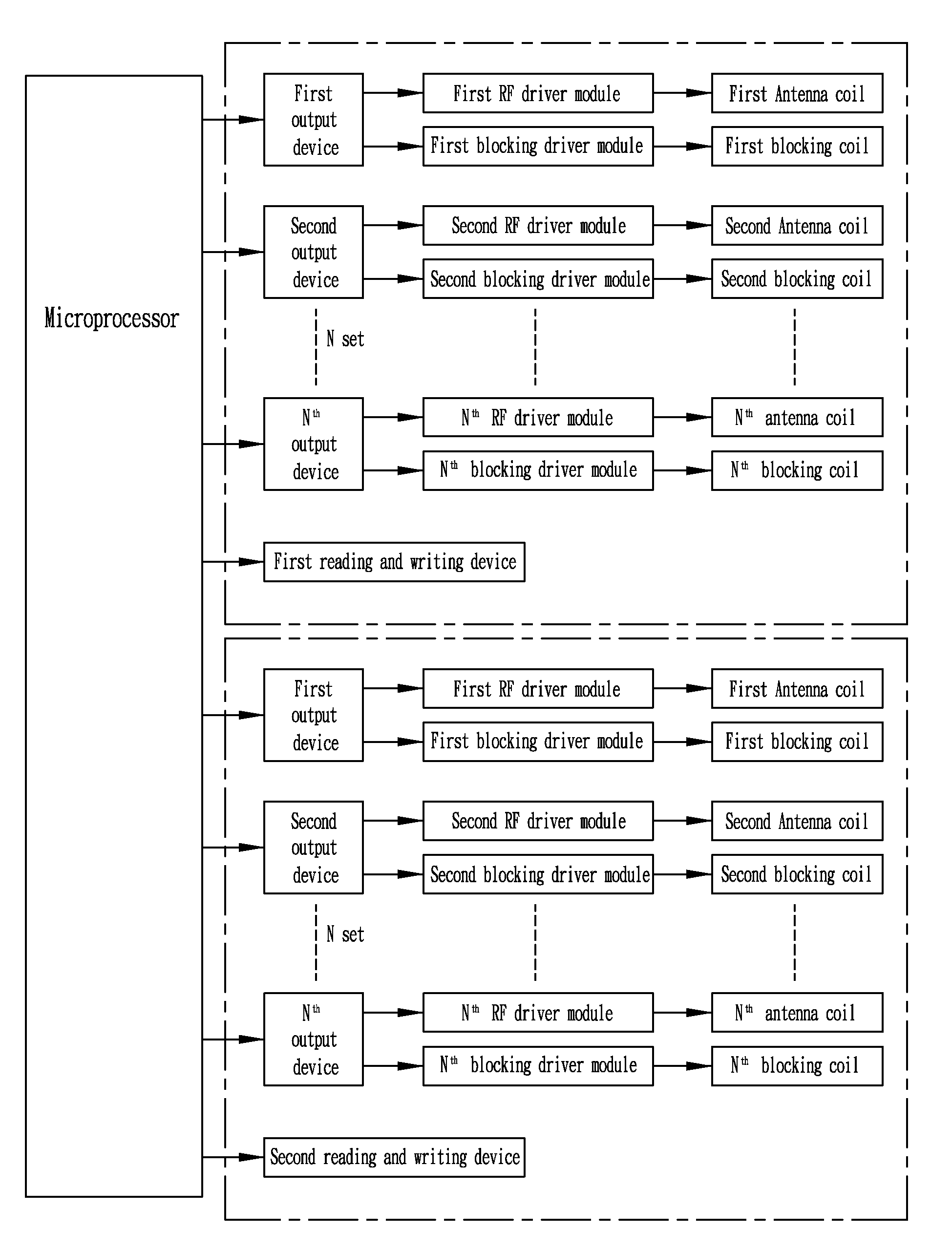
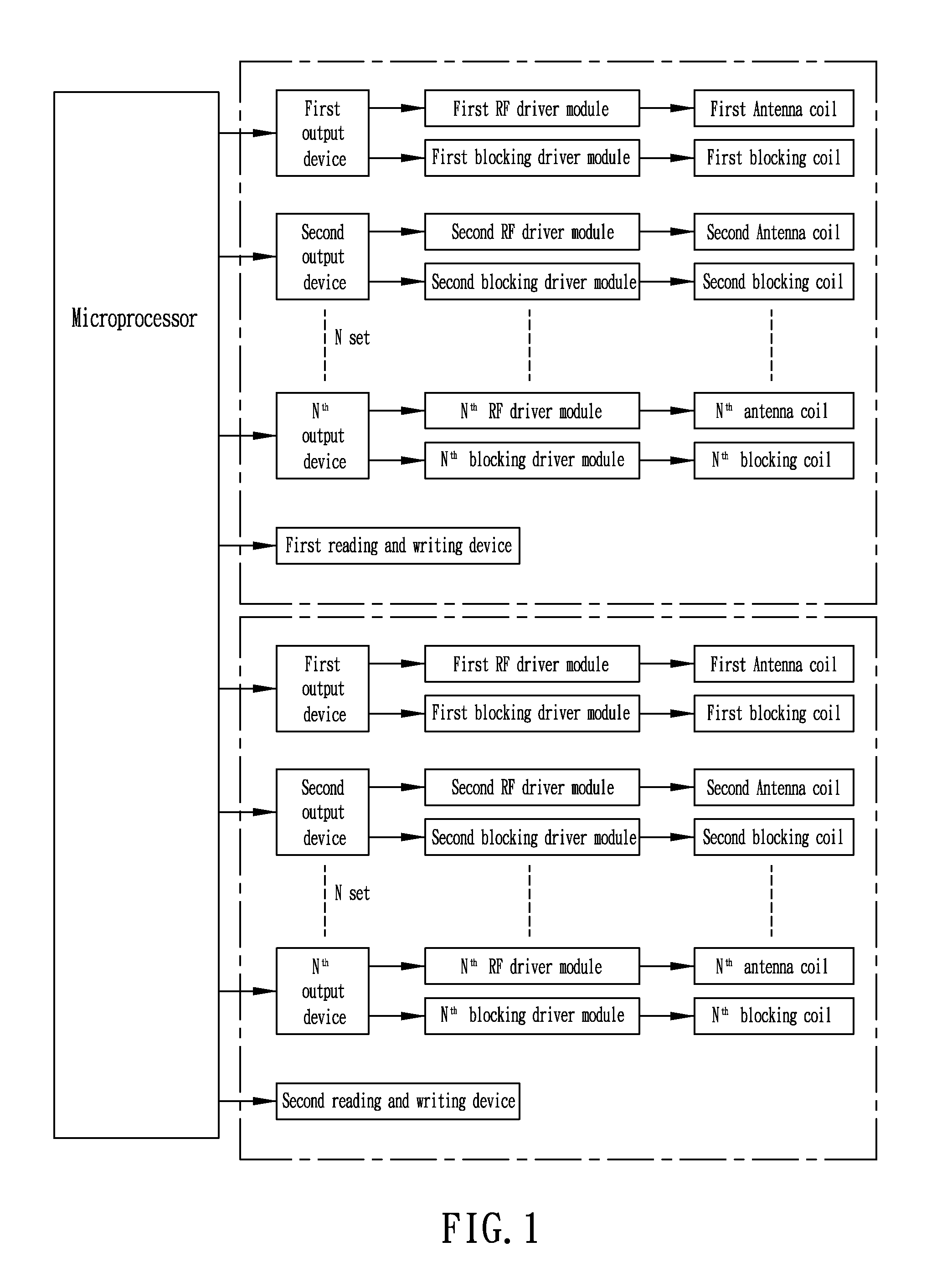
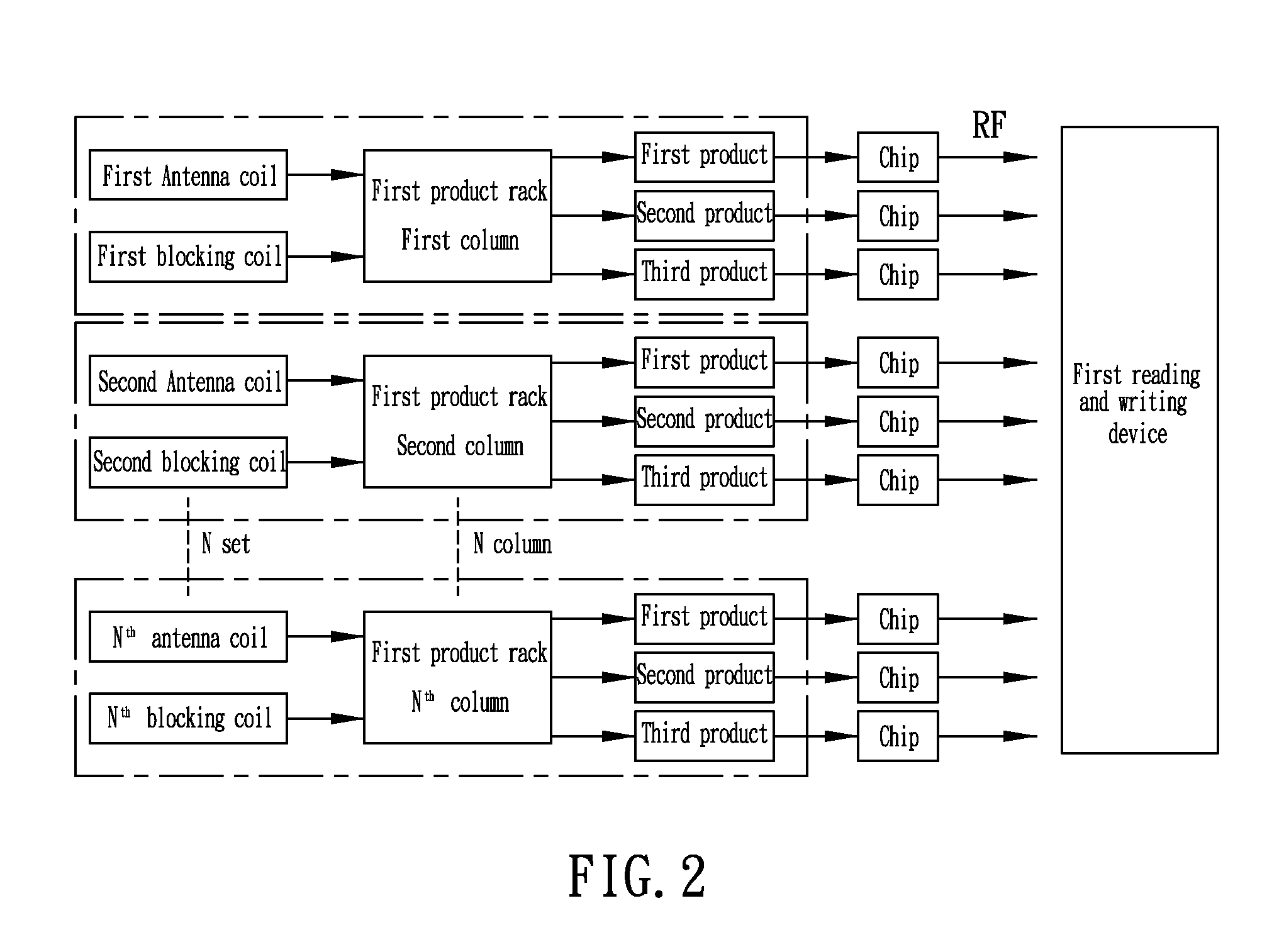
[0012]In FIGS. 1˜3 is shown a radio frequency management system comprising, for example, two radio frequency management devices that are distinguished by reading and writing devices, i.e. each radio frequency management device comprises multiple reading units that are connected in parallel to one same reading and writing device. Each reading unit comprises multiple RF (radio-frequency) driver modules (first RF driver module, second RF driver module, . . . Nth RF driver module) and multiple blocking driver modules (first blocking driver module, second blocking driver module, . . . Nth blocking driver module). Each RF driver module is adapted for driving a respective antenna coil. Each blocking driver module is adapted for driving a respective blocking coil to block the associated antenna coil. Each RF driver module and the associated blocking driver module are electrically connected to one respective output device (first output device, second output device, . . . Nth output device). ...


PUM


Abstract

A radio frequency management device includes a microprocessor, output devices connected in parallel to the microprocessor, reading units respectively connected to the output devices, each reading unit comprising an antenna coil, a blocking coil, a radio frequency driver module for driving the antenna coil, and a blocking driver module for driving said blocking coil to shield the antenna coil from the radio frequency driver module, and a reading and writing device connected to the microprocessor. The microprocessor controls the output devices in such a manner that only one radio frequency driver module is activated to drive the associated antenna coil at any time while the other antenna coils of the other reading units are shielded from the associated radio frequency driver modules by the associated blocking coils; the reading units are processed one after another in a proper order.

Description

BACKGROUND OF THE INVENTION[0001](a) Field of the Invention[0002]The present invention relates to radio frequency technology and more particularly to a radio frequency management system for use in a shop inventory control system.[0003](b) Description of the Prior Art[0004]Many different types of radio frequency identification devices are known. In a typical application of radio frequency identification, each product to be identified carries a chip that has identification data stored in a read only memory or read write memory therein, and a reading apparatus is operated to transmit a radio frequency signal to the chip via an antenna so that the storage data of the chip is fetched and sent back to the antenna by means of a radio carrier. The fetched data is then demodulated for further data processing. This technology can be applied to product distribution management to save much management time and labor. It has become increasingly popular for radio frequency management to be applied...

Claims


Application Information

Patent Timeline
Patent Type & Authority Applications(United States)
IPC IPC(8): H04B1/10
CPCG06K2017/0051G06K7/0008
Inventor HUANG, KENG-YING
Owner J LINK TECH CORP
Why Eureka
Try Eureka