Crushable body strength adjusting device for a vehicle

a technology of body strength and adjusting device, which is applied in the direction of bumpers, vehicle components, vehicular safety arrangments, etc., can solve the problems of insufficient shock absorption effect, steep increase of load, and ineffective absorption of collision load input from the front, so as to enhance the shock absorption effect and efficient crush

Inactive Publication Date: 2008-08-07
HONDA MOTOR CO LTD
View PDF3 Cites 37 Cited by
  • Summary
  • Abstract
  • Description
  • Claims
  • Application Information

AI Technical Summary

Benefits of technology

[0010]The present invention has been accomplished with the above circumstance in view, and it is a first object of the present invention to prevent a lateral force in a widthwise direction of a vehicle from being input to a variable crush-strength device when a collision load is applied to a bumper beam in a longitudinal direction of a vehicle body, whereby the variable crush-strength device is efficiently crushed to enhance a shock-absorbing effect.

Problems solved by technology

Thus, the variable crush-strength devices fall down and are inclined outward of the vehicle body, leading to a possibility that the collision load being input from the front cannot be effectively absorbed.
However, in the case where a load acting in a direction inclined with respect to the longitudinal direction of the vehicle body is input to the bumper beam upon diagonal collision of a vehicle, the buckling plates of the variable crush-strength devices fall down in right and left directions without being buckled, leading to a possibility that a sufficient shock-absorbing effect cannot be exhibited.
However, if a buckling plate is formed of an iron material or an aluminum material, the load steeply increases with an increase in the amount of deformation of the buckling plate to reach a peak and then gradually decreases, leading to a difficulty in maintaining a constantly high load level.
On the other hand, if a buckling plate is formed of shape memory alloy, the load steeply increases with an increase in the amount of deformation of the buckling plate to reach a peak and then steeply decreases to reach a bottom, and further gradually increases from the bottom, also leading to a difficulty in maintaining a constantly high load level.

Method used


Image

  • Crushable body strength adjusting device for a vehicle
  • Crushable body strength adjusting device for a vehicle
  • Crushable body strength adjusting device for a vehicle

Examples


first embodiment

[0073]The operation of the present invention having the above-described arrangement will be described blow.

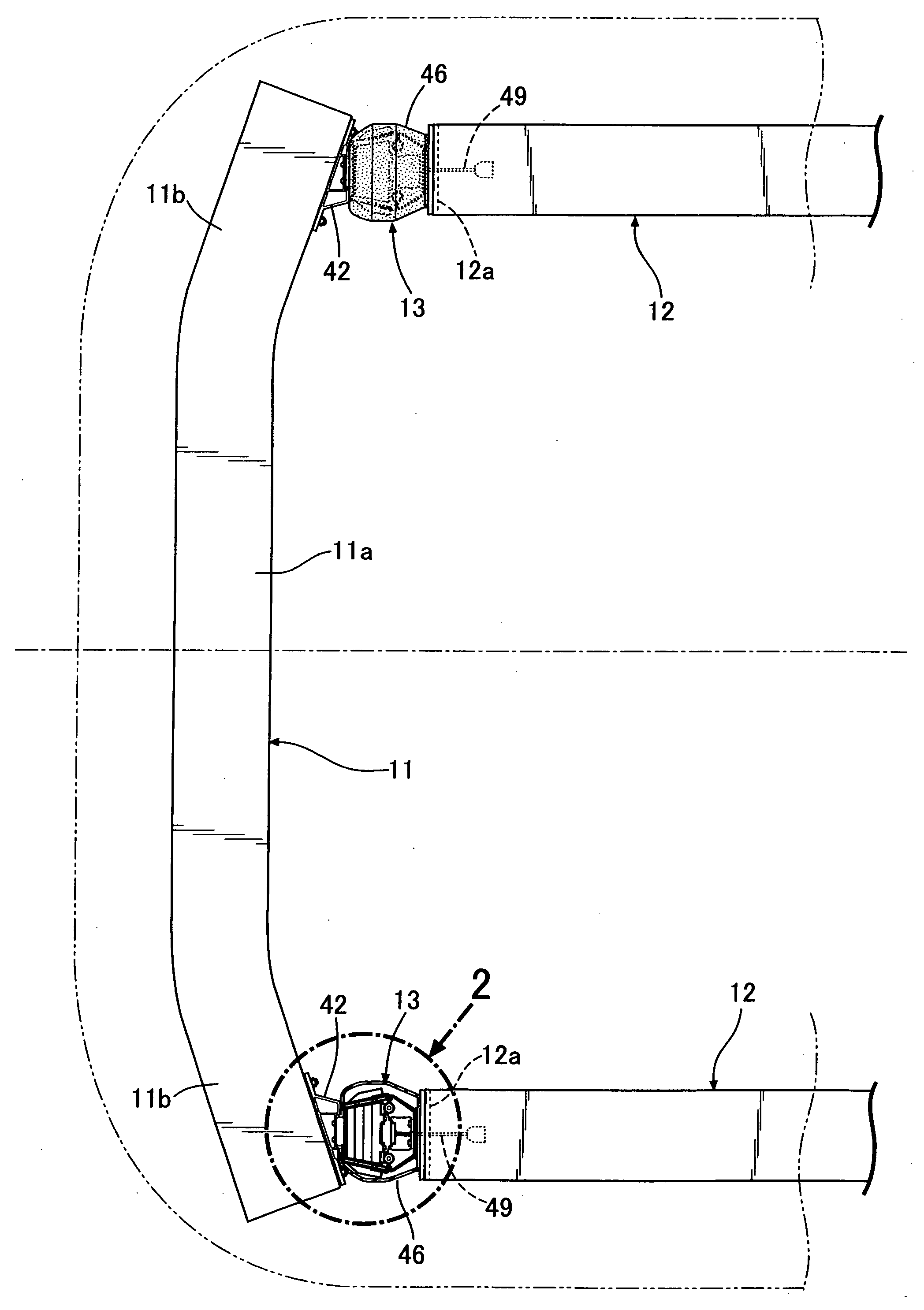
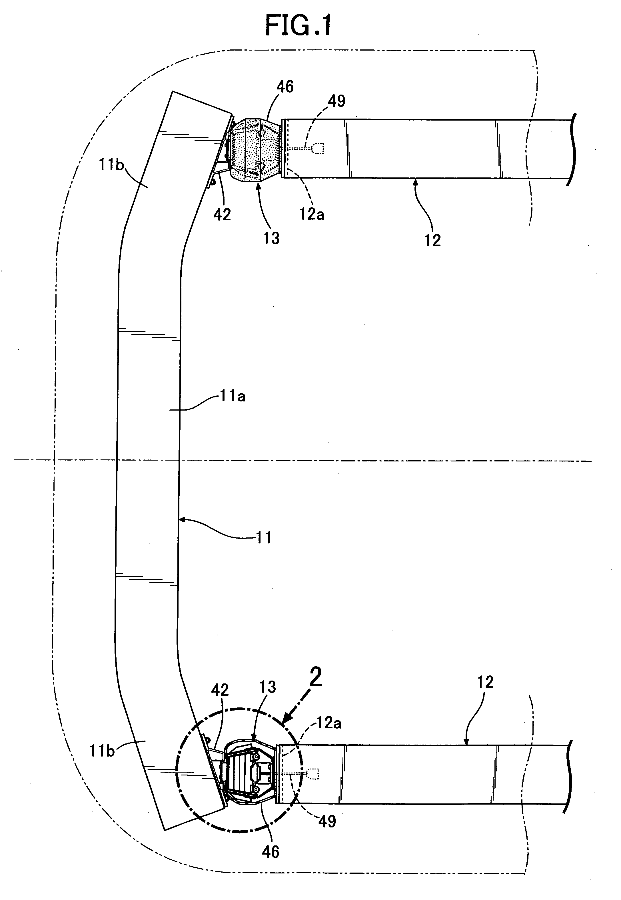
[0074]In an normal state, the locking pins 27, 27 of the variable crush-strength device 13 protrude from the opposite ends of the bush 26, and therefore the engagement portions 27b, 27b at the tip ends of the locking pins 27, 27 are in engagement with the receiving member 51, 51 of the hinge plate 22 (see solid lines in FIGS. 5 and 6). In this state, when the vehicle collides head-on with an object thereby applying a collision load to the bumper beam 11 in the rearward direction of the vehicle body, the front base plate 35 and the rear base plate 16 of the variable crush-strength device 13 disposed between the bumper beam 11 and the front side frame 12 are longitudinally compressed.

[0075]At this time, as shown in FIGS. 9A to 9C, the lateral movements of the locking pin-supporting portions 22a, 22a of the hinge plate 22 are restricted by the locking pins 27, 27, and the rearward...

fourth embodiment

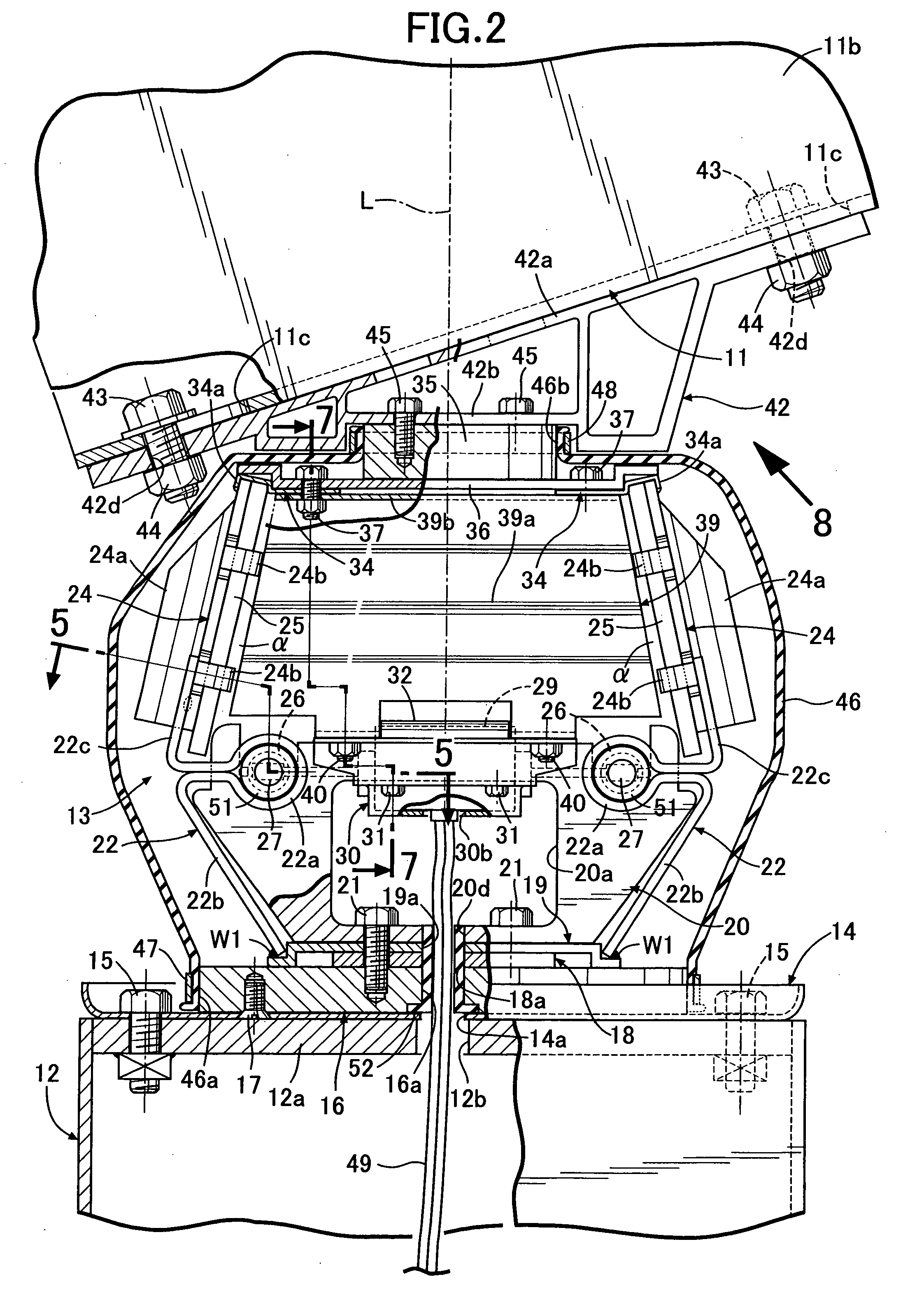
[0098]The directions of extension of the two first elongate bolt holes 11c, 11c formed in the upper and lower walls of the inclined portion 11b of the bumper beam 11, are not parallel to a direction of the inclined portion 11b inclined rearward of the vehicle body, and are inclined more steeply than the inclination of the inclined portion 11b. More specifically, the inclined portion 11b is inclined by an angle γ with respect to the direction of extension of the body portion 11a of the bumper beam 11 (in the widthwise direction of the vehicle), and also the direction of extension of the first bolt hole 11c is inclined further rearward by an angle δ with respect to the direction of extension of the inclined portion 11b. Therefore, the direction of extension of the first bolt hole 11c is inclined by an angle ε=γ+δ with respect to the direction of extension of the body portion 11a. In the fourth embodiment γ is set to be equal to δ, and hence the angle ε formed by the first bolt hole 11...

ninth embodiment

[0115]The second buckling plate 25 in the ninth embodiment as shown in FIG. 23B has a characteristic that the load steeply increases with an increase in displacement amount, but the increasing rate is decreased so that the load is moderately increased thereafter. In this case, the first buckling plate 24, which is made of an iron material or the like, and the second buckling plate 25, whish is made of shape memory alloy or the like, are formed to have the same length, and the compressions of the first buckling plate 24 and the second buckling plate 25 simultaneously start at the time point t1. In this manner, a characteristic (see the solid line) combining the loads on the first and second buckling plates 24 and 25 can approximate a generally constant ideal characteristic.

[0116]The exemplary embodiments of the present invention have been described above, but various changes in design may be made without departing from the subject matter of the present invention.

[0117]For example, in...


PUM


Abstract

A vehicle body strength adjusting system is provided in which a bumper beam includes a body portion which extends in a widthwise direction of a vehicle and inclined portions which extend from left and right opposite ends of the body portion and which are inclined in a longitudinal direction of the vehicle body. Further, the vehicle body strength adjusting system includes a variable crush-strength device which is disposed between the inclined portions of the vehicle body frames, which can be crushed when a collision with the vehicle occurs, and which has a variable crush-strength. A first bolt hole is formed in each of the inclined portions of the bumper beam and a second bolt hole is formed in the mounting bracket of the variable crush-strength device. At least one of the first bolt hole and the second bolt hole is an elongate hole. The first bolt hole and the second bolt hole are fastened to each other by a bolt.

Description

CROSS-REFERENCE TO RELATED APPLICATIONS[0001]The present invention claims priority under 35 USC §119 based on Japanese patent application numbers 2007-25845 filed 5 Feb. 2007, 2007-25846 filed 5 Feb. 2007, 2007-25848 filed 5 Feb. 2007 and 2007-229505 filed 4 Sep. 2007. The subject matter of these priority documents are incorporated by reference herein.BACKGROUND OF THE INVENTION[0002]1. Field of the Invention[0003]The present invention relates to a crushable body strength adjusting system in a vehicle, comprising a device which is disposed between a bumper beam and a vehicle body frame, can be crushed upon reception of a collision load in the longitudinal direction of the vehicle body, and has a variable crush-strength.[0004]2. Description of the Related Art[0005]Japanese Patent Application Laid-open No. 2006-8106 discloses a vehicle body strength adjusting system comprising: a bumper beam mounted at front ends of front side frames of an automobile, the bumper beam including a pair ...

Claims


Application Information

Patent Timeline
Patent Type & Authority Applications(United States)
IPC IPC(8): B60R19/18
CPCB60R19/34B60R2019/262B60R19/36
Inventor SUZUKI, SHUNJIURUSHIYAMA, YUTAGUNJI, YASUAKI
Owner HONDA MOTOR CO LTD
Why Eureka
Try Eureka