Output control apparatus and method for field winding type dynamo-electric machine

a technology of output control and dynamo-electric machine, which is applied in the direction of electric generator control, dynamo-electric converter control, transportation and packaging, etc., can solve the problems of insufficient generation torque control accuracy, small error, and low calculation accuracy

Active Publication Date: 2008-08-07
DENSO CORP +1
View PDF9 Cites 45 Cited by
  • Summary
  • Abstract
  • Description
  • Claims
  • Application Information

AI Technical Summary

Benefits of technology

[0018]According to a main feature of the invention, the exciting current supplying apparatus for use in the field winging type dynamo-electric machine includes an exciting current detecting circuit, a rotation speed detecting circuit, a generation torque calculation circuit, and an exciting current control circuit. The exciting current detecting circuit is designed to measure an exciting current of a flux winding of the field winging type dynamo-electric machine to output the result of the measurement as a detected exciting current value thereof. The rotation speed detecting circuit is designed to detect the rotation speed of the rotor of the field winging type dynamo-electric machine to output the result of the detection as a detected rotation speed. The generation torque calculation circuit is designed to estimate the output generation torque of the dynamo-electric machine by making reference to the predetermined table that contains a relation between at least the detected value o

Problems solved by technology

This method, however, has suffered a problem of low calculation accuracy in the determined exciting current which is calculated based on a command value of the generation torque.
This problem has created another problem that not-a-small error can occur between the demanded ge

Method used


Image

  • Output control apparatus and method for field winding type dynamo-electric machine
  • Output control apparatus and method for field winding type dynamo-electric machine
  • Output control apparatus and method for field winding type dynamo-electric machine

Examples


specific example 1

of Correction of Exciting Current

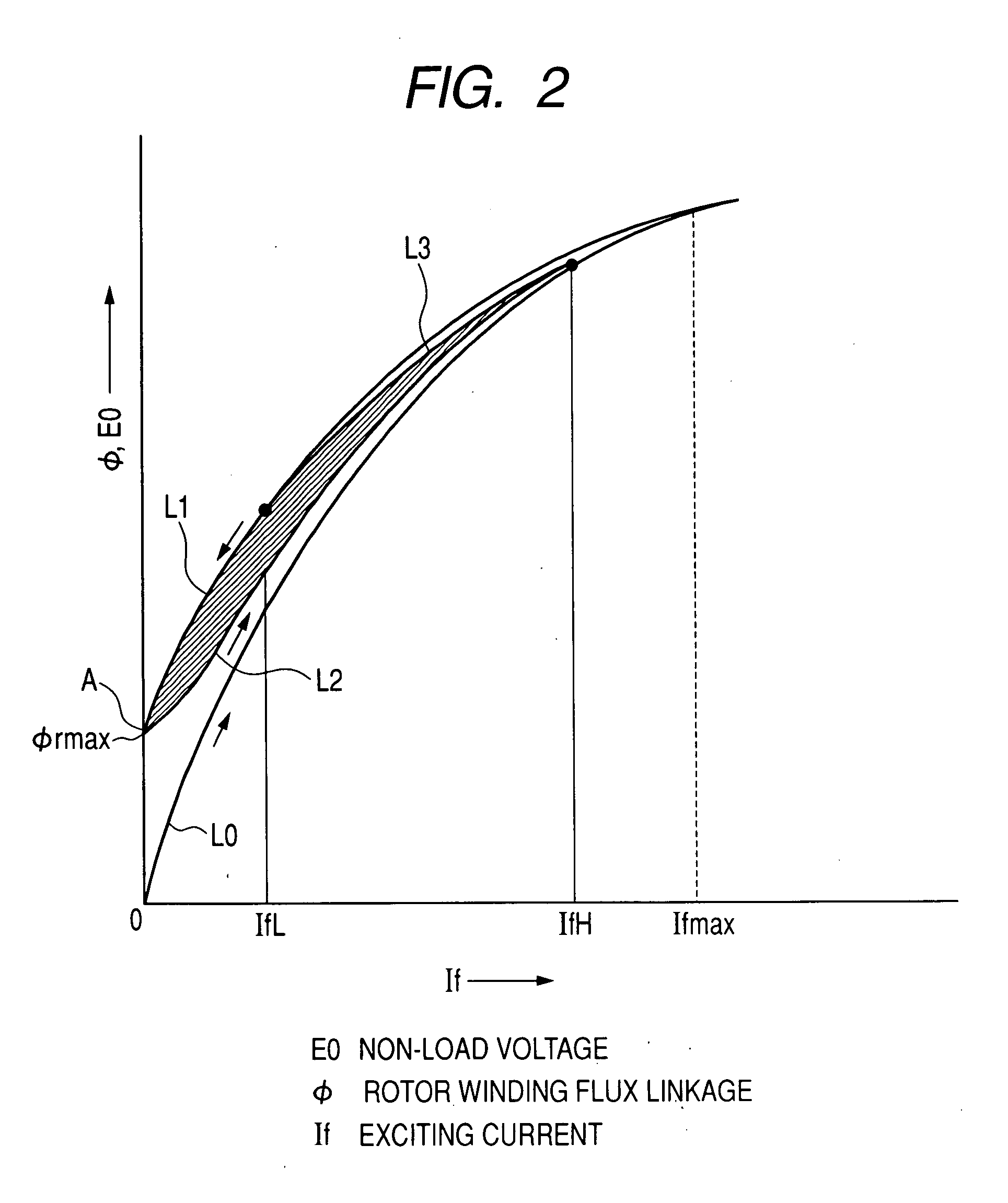
[0067]The specific example 1 of correction of exciting current will now be explained referring to FIG. 2.

[0068]The correction of exciting current substantially corrects an error ΔIf=Ifm−If between the exciting current detection value If and a memory creation exciting current Ifm which was used when creating the above described torque map and an generation current map. The error ΔIf is generated due to hysteresis characteristics of a magnetic material configuring a magnetic circuit in which field flux flows. Generation of the error ΔIf caused by hysteresis characteristics will be hereafter explained.

[0069]FIG. 2 is an illustration of exciting current and an rotor coil linkage magnetic flux amount (also referred to as a stator coil linkage magnetic flux) φ. As well known, the rotor coil linkage magnetic flux amount is proportional to no-load voltage Eo of the rotor coil. FIG. 2 shows only the first quadrant. L0 represents an initial magnetization chara...

specific example 2

of Correction of Exciting Current

[0084]Specific example 2 of correction of exciting current will be explained. In the specific example 2, the characteristic lines L2 and L3 have been stored in advance. In Case 3, torque estimation is carried out by determining two rotor coil linkage magnetic flux amounts φ by substituting the exciting current detection value If to the characteristic lines L2 and L3, substituting the average magnetic flux values of these to the characteristic line L2 to determine the corrected exciting current value, and substituting the corrected exciting current value to the above described first map. Note that torque estimation may be carried out by substituting the above described average magnetic flux value to the characteristic line L3 to determine the corrected exciting current value, and substituting the corrected exciting current value to the above described second map.

specific example 3

of Correction of Exciting Current

[0085]Specific example 3 of correction of exciting current will be explained. In the specific example 3, whether the immediately preceding exciting current tends to increase or tends to decrease in the above described specific example 2 has been determined based on the history of the immediately preceding exciting current detection value.

[0086]Next, when it tends to increase, torque estimation is carried out in Case 3 by determining two rotor coil linkage magnetic flux amounts φ by substituting the exciting current detection value If to the characteristic lines L2 and L3, determining the corrected exciting current value by substituting a value determined by subtracting a predetermined value Δφ from the average magnetic flux value of these to the characteristic line L2, and substituting the corrected exciting current value to the above described first map.

[0087]Next, when it tends to decrease, torque estimation is carried out in Case 3 by determining ...


PUM


Abstract

A control apparatus for controlling an exciting current of a field winding type dynamo-electric machine having an exciting winding so as to obtain a demanded output thereof comprises an exciting current detecting circuit being configured to detect an exciting current of the field winding type dynamo-electric machine, a rotation speed detecting circuit being configured to detect a rotation speed of a rotor of the field winding type dynamo-electric machine, an output estimating circuit being configured to estimate an output of the field winding type dynamo-electric machine, an exciting current control circuit being configured to correct the exciting current of the field winding type dynamo-electric machine so as to obtain the demanded output and to supply the corrected exciting current to an exciting winding of the field winding type dynamo-electric machine considering a multi-valued functionality of the output of the field winding type dynamo-electric machine with respect to the exciting current.

Description

CROSS REFERENCE TO RELATED APPLICATION[0001]The present application relates to and incorporates by reference Japanese Patent Application No. 2006-142841 filed on May, 23, 2006.BACKGROUND OF THE INVENTION[0002]1. The Field of the Invention[0003]The present invention relates to an output control apparatus and method designed to output a commanded mechanical and / or electrical output of a field winging type dynamo-electric machine or an induction motor by controlling an exciting current thereof, in particular to a control apparatus and method for supplying an appropriate exciting current is supplied to the field winging type dynamo-electric machine or the induction motor so as to obtain the demanded mechanical and / or electrical output. For example, the above mentioned mechanical and / or electrical outputs of the field winging type dynamo-electric machine or an induction motor are a generation torque and an generation electrical current. Furthermore, the present invention relates to an ou...

Claims


Application Information

Patent Timeline
IPC IPC(8): H02P9/14H02J7/16H02J7/24
CPCB60L15/025Y02T10/643H02P21/14Y02T10/64H02J7/16H02J7/24H02P9/30
Inventor KIMURA, NORIHITOTANAKA, KATSUNORI
Owner DENSO CORP
Why Eureka
Try Eureka