
Sound reproducing system and sound reproducing method

a sound reproduction system and sound technology, applied in the direction of electrical transducers, stereophonic arrangments, gain control, etc., can solve the problems of high cost disadvantage, noise caused by sound leakage, and the inability to place the above-described six speakers to reproduce multi-channel surround sound, etc., to achieve the effect of improving the localization of sound images

Inactive Publication Date: 2008-08-07
SONY CORP
View PDF32 Cites 46 Cited by
  • Summary
  • Abstract
  • Description
  • Claims
  • Application Information

AI Technical Summary

Benefits of technology

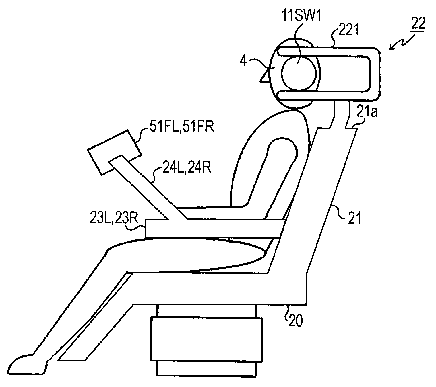
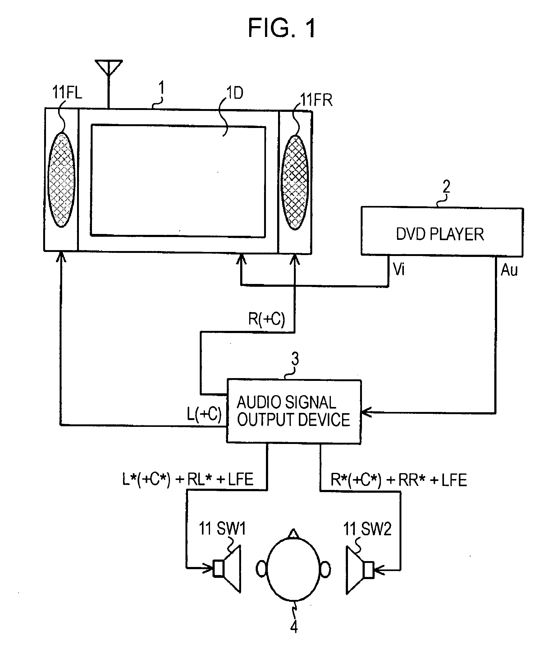
[0018]In this previously suggested invention, two speakers are held near the ears of a listener and thus the listener can listen to sound with a sufficient volume even if the sound is actually output from the speakers in not so large volume. Accordingly, the sound propagated to adjacent houses is reduced.
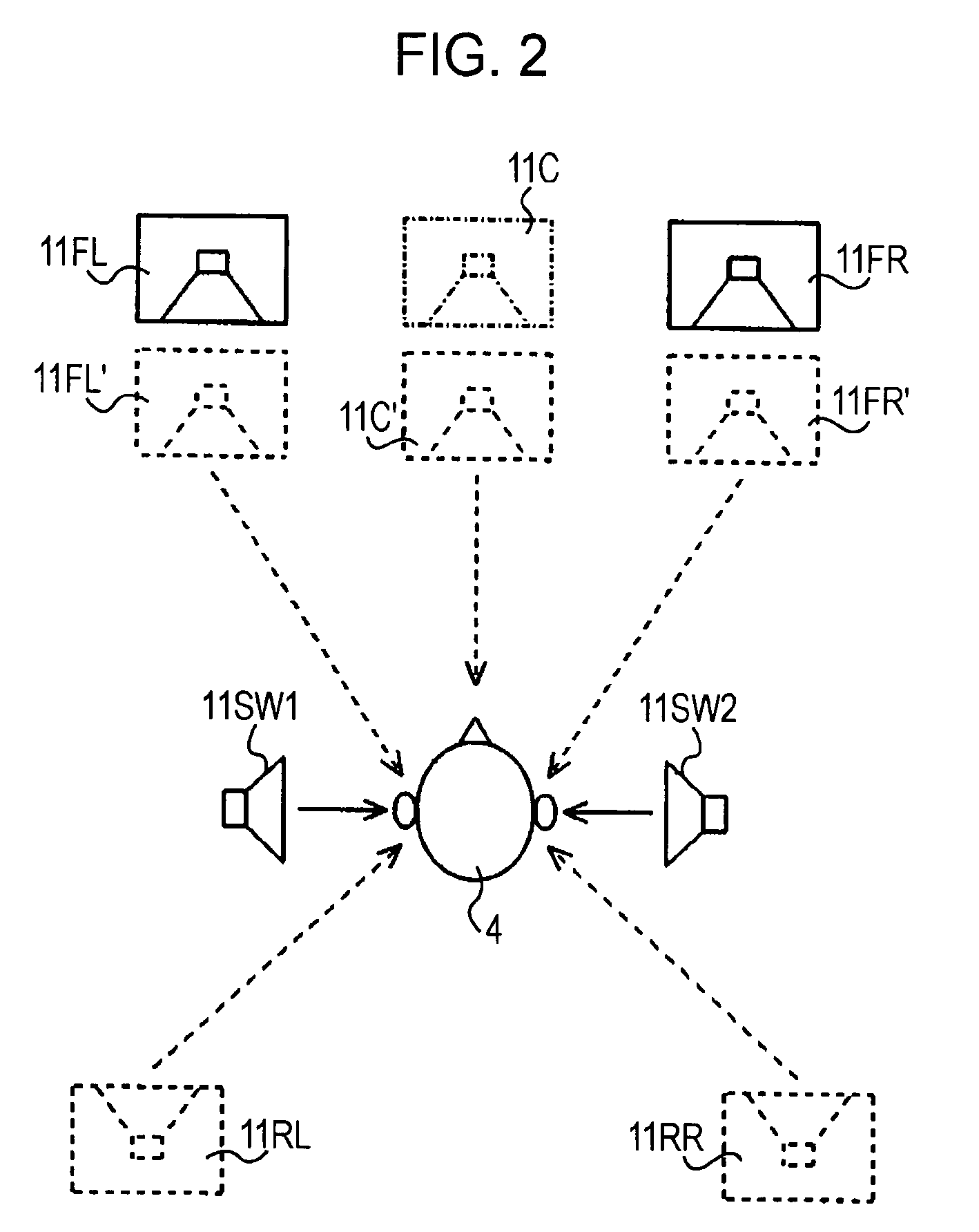
[0028]The gain control of the audio signals of the plurality of channels performed by the control means enables improvement in sound image localization of sound of a channel in which a sound image is localized in a position in a front direction of a listener, such as the center channel where the sound image localization is difficult to obtain, even when sound of a plurality of channels is reproduced by using the virtual sound source process.
[0029]According to an embodiment of the present invention, sound image localization of sound of a channel in which a sound image is localized in a position in a front direction of a listener, such as a center channel where the sound image localization is difficult to obtain, can be improved even when sound of a plurality of channels is reproduced by using the virtual sound source process.

Problems solved by technology

However, in a relatively small room, it may be impossible to make room for placing the above-described six speakers to reproduce multi-channel surround sound.
Also, the necessity for six speakers and amplifiers leads to high cost disadvantageously.
Noise caused by sound leakage is also a problem.

Method used


Image

  • Sound reproducing system and sound reproducing method
  • Sound reproducing system and sound reproducing method
  • Sound reproducing system and sound reproducing method

Examples


embodiment and modification

Another Embodiment and Modification

[0175]In the example illustrated in FIGS. 10A to 10C, the audio signals on which the virtual sound source process is performed to be supplied to the speakers 11SW1 and 11SW2 placed near the ears of the listener 4 include signals of “full at the ears” including the center channel and signals of “without C at the ears” not including the center channel. In this case, the virtual sound source process is performed or not performed on the audio signals of the center channel depending on cases, which is complicated.

[0176]As a gain control method not requiring removal or addition of the center channel, the following simple method can be used. That is, reproducing of sound by the real speakers provided in front of the listener 4 and reproducing of sound of virtual sound image localization by the speakers 11SW1 and 11SW2 are used together. Also, gain control is performed to increase the volume of the audio signals of the channel to be supplied to the real sp...


PUM


Abstract

A sound reproducing system includes a first speaker that is supplied with audio signals of a first channel and that is placed so that a reproduced sound image generated by the audio signals of the first channel is localized in a position in a front direction of a listener; a pair of second speakers that are supplied with audio signals on which a virtual sound source process is performed; a virtual sound source processing unit to perform the virtual sound source process on the audio signals of a plurality of channels; a volume detecting unit to detect the volumes of the first channel and the other channels; a volume comparing unit to compare the volume of the first channel with each of the volumes of the other channels; and a control unit to control the gains of the audio signals of the first channel and the other channels.

Description

CROSS REFERENCES TO RELATED APPLICATIONS[0001]The present invention contains subject matter related to Japanese Patent Application JP 2006-256803 filed in the Japanese Patent Office on Sep. 22, 2006, the entire contents of which are incorporated herein by reference.BACKGROUND OF THE INVENTION[0002]1. Field of the Invention[0003]The present invention relates to a sound reproducing system to reproduce sound by performing a virtual sound source process on audio signals of part of a plurality of channels. The present invention also relates to a sound reproducing method in the sound reproducing system.[0004]2. Description of the Related Art[0005]A video and sound reproducing system called a “home theater system” has been becoming widespread. In the video and sound reproducing system, video is reproduced from a DVD (digital versatile disc) or the like by displaying it on a display having a relatively large screen, while sound is reproduced in a multi-channel surround sound method, recentl...

Claims


Application Information

Patent Timeline
IPC IPC(8): H04R5/02
CPCH04R1/025H04R1/028H04S2420/01H04R2420/07H04S3/008H04R3/12
Inventor YOKOTA, TEPPEI
Owner SONY CORP
Learn More