Communication Device, Communication System, Communication Method, Communication Program, and Communication Circuit

Active Publication Date: 2008-08-07
SHARP KK
View PDF77 Cites 18 Cited by
  • Summary
  • Abstract
  • Description
  • Claims
  • Application Information

AI Technical Summary

Benefits of technology

[0034]According to the disconnection sequence, no communication is needed for a disconnection of the network layers be

Problems solved by technology

Communication overhead, that is, the time between the start of a connection process and the start of a data transmission,

Method used


Image

  • Communication Device, Communication System, Communication Method, Communication Program, and Communication Circuit
  • Communication Device, Communication System, Communication Method, Communication Program, and Communication Circuit
  • Communication Device, Communication System, Communication Method, Communication Program, and Communication Circuit

Examples


embodiment 1

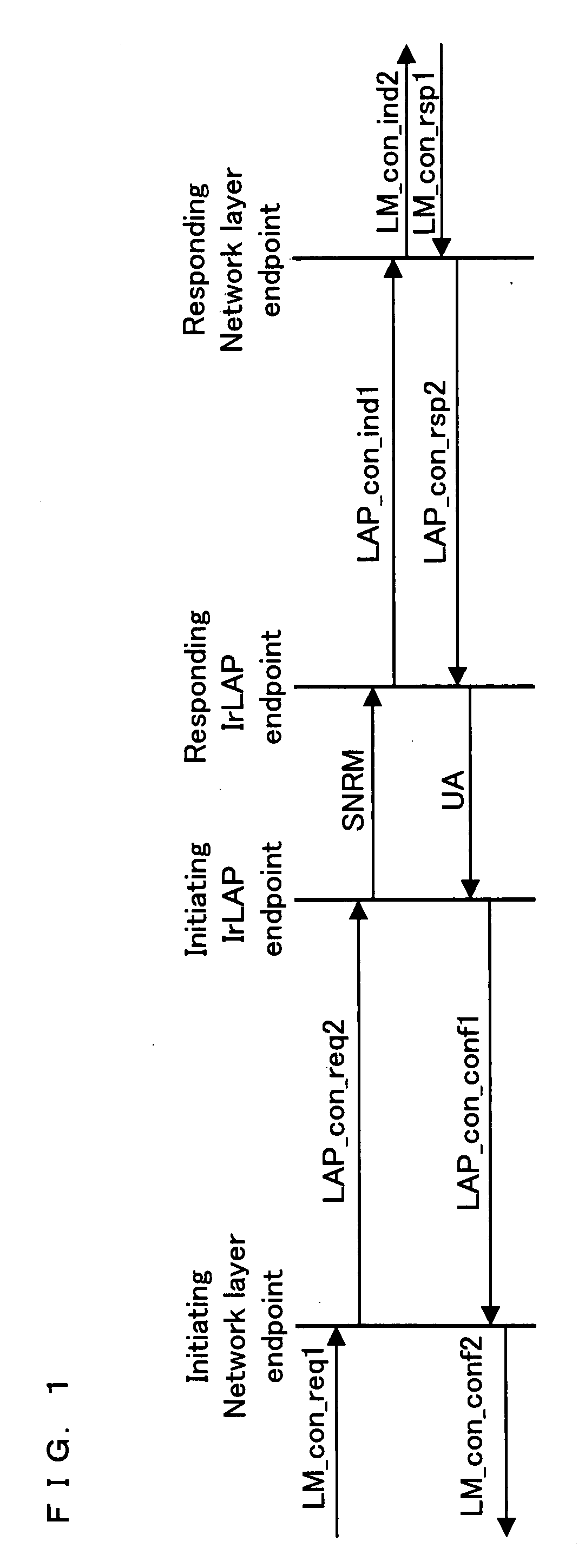
[0100]The following will describe an embodiment of the present invention in reference to FIGS. 1, 2.

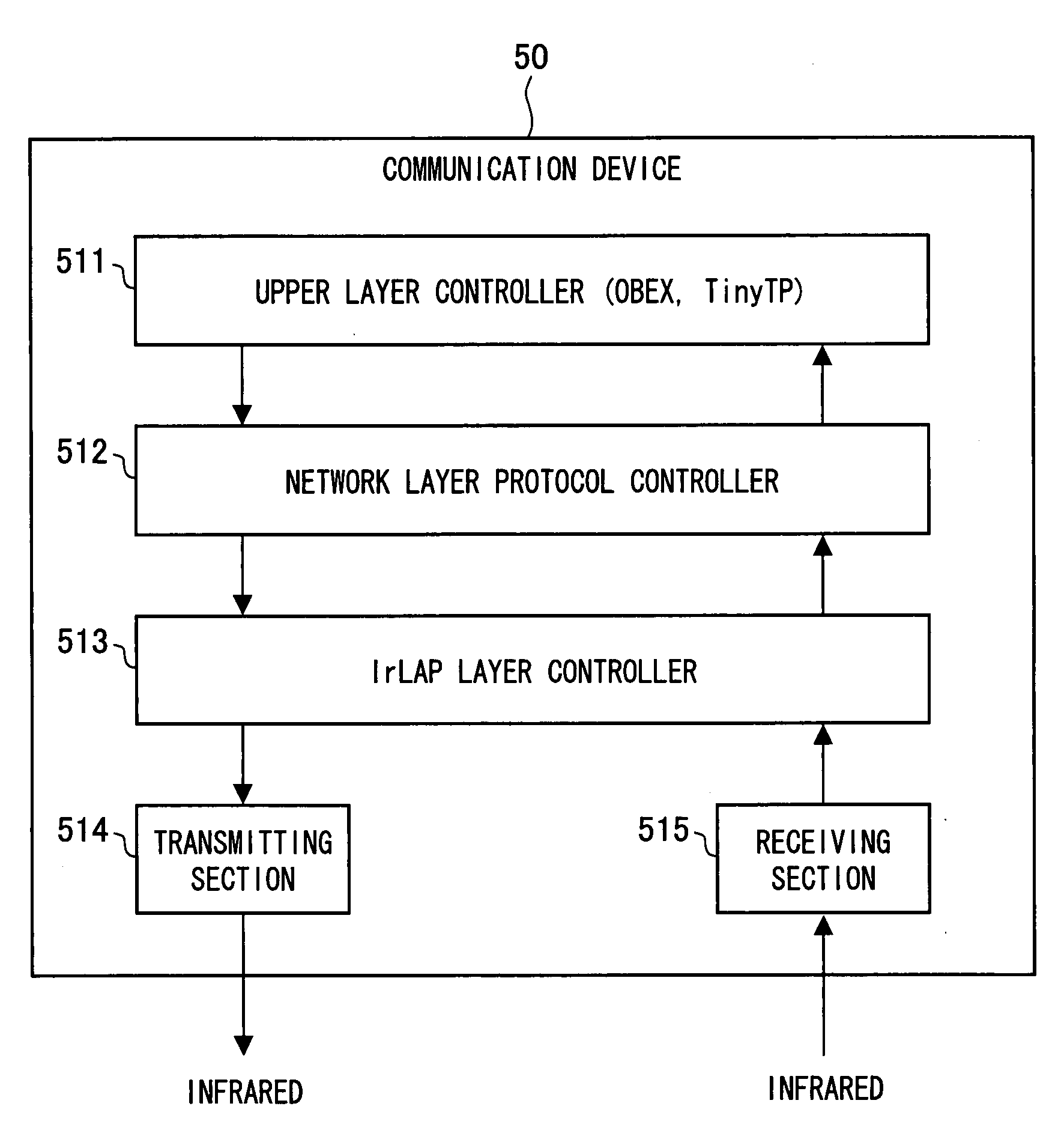
[0101]A signal sequence figure for the present embodiment is shown in FIG. 1, and a block diagram is shown in FIG. 5. This is by no means intended to be limiting the invention. FIG. 5 shows OBEX and TinyTP as the upper layer; this is again by no means intended to be limiting the invention. FIG. 5 shows a network layer protocol controller as a single layer; the functionality of that controller may be incorporated into the upper layer or the lower layer, in which case there may not be an independent network layer protocol controller. The modules in FIG. 5 may be implemented either in software or hardware provided that their functions are properly realized.

[0102]As shown in FIG. 1, first of all, the upper layer controller 511 of the primary station issues a connection request command 1 (LM_con_req1) containing data needed for a connection. Upon receiving the connection request command 1,...

embodiment 2

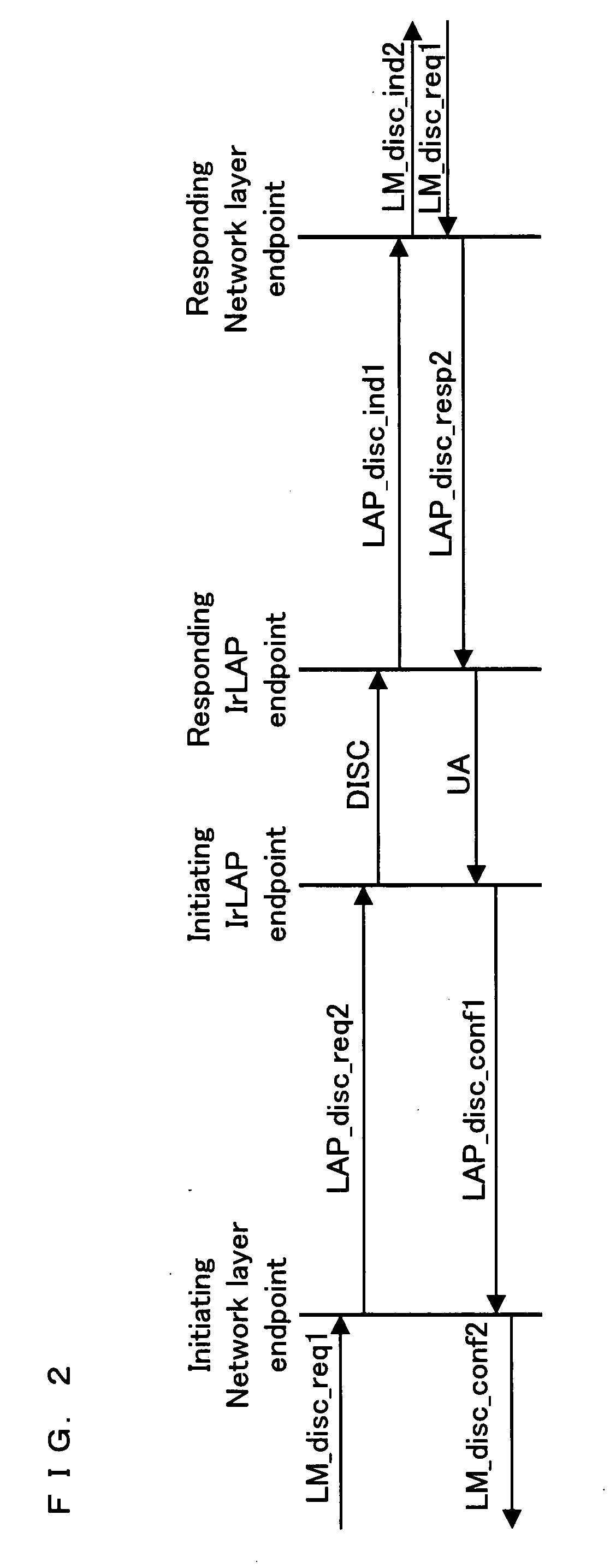
[0110]The following will describe another embodiment of the present invention in reference to FIGS. 2, 5.

[0111]A signal sequence figure for the present embodiment is shown in FIG. 2, and a block diagram is shown in FIG. 5. This is by no means intended to be limiting the invention. FIG. 5 shows OBEX and TinyTP as the upper layer; this is again by no means intended to be limiting the invention. FIG. 5 shows a network layer protocol controller as a single layer; the functionality of that controller may be incorporated into the upper layer or the lower layer, in which case there may not be an independent network layer protocol controller. The modules in FIG. 5 may be implemented either in software or hardware provided that their functions are properly realized.

[0112]As shown in FIG. 2, first of all, for a disconnection, the upper layer controller 511 of the primary station issues a disconnection request command 1 (LM_disc_req1) containing data needed for a disconnection. Upon receiving ...

embodiment 3

[0121]The following will describe another embodiment of the present invention in reference to FIGS. 5, 6.

[0122]A signal sequence figure for the present embodiment is shown in FIG. 6, and a block diagram is shown in FIG. 5. This is by no means intended to be limiting the invention. FIG. 5 shows OBEX and TinyTP as the upper layer; this is again by no means intended to be limiting the invention. FIG. 5 shows a network layer protocol controller as a single layer; the functionality of that controller may be incorporated into the upper layer or the lower layer, in which case there may not be an independent network layer protocol controller. The modules in FIG. 5 may be implemented either in software or hardware provided that their functions are properly realized.

[0123]As shown in FIG. 6, first of all, the upper layer controller 511 of the primary station issues a connection request command 1 (LM_con_req1) containing data needed for a connection. In the issuing, information on whether the ...


PUM


Abstract

The present invention is a network layer protocol used for free-space optical transmission utilizing an LED or LD as a light source. In order to connect to a device, the network layer issues a connection request command (LAP_con_req2) to a lower layer when the network layer has received a connection request command (LM_con_req1) from an upper layer. Furthermore, when the network layer has received a connection confirmation command reception notification (LAP_con_conf1) from the lower layer, the network layer issues a connection confirmation command reception notification (LM_con_conf2) to the upper layer without issuing a data transfer request command to the lower layer. Accordingly, the invention provides a network layer protocol with which time for a connection or disconnection is reduced.

Description

TECHNICAL FIELD[0001]The present invention relates to communication devices, communication systems, communication methods, communication programs, and communication circuits for wireless or wired communication.BACKGROUND ART[0002]The IrDA (Infrared Data Association) scheme is one of currently known free-space optical communication standards. The IrDA scheme uses IrLMP (Infrared Link Management Protocol) as the network layer protocol.[0003]In IrLMP, the connection and disconnection with other devices is carried out primarily by station control which controls that connection and disconnection via an IrLAP (Infrared Link Access Protocol) which is a lower layer and a LSAP (Link Service Access Point) which logically controls the connection.[0004]To connect to a device, as shown in FIG. 3, when the LSAP of the primary station (initiating station) receives, from the upper layer, a connection request command 1 (LM_con_req1) which contains data needed to establish a connection to the seconda...

Claims


Application Information

Patent Timeline
IPC IPC(8): G06F15/16H04B10/00G06F15/173
CPCH04B10/1125H04L69/32H04L29/06H04L69/325H04L9/40
Inventor NAOE, HITOSHIFUKAE, FUMIHIROSAKAI, KOJIOHSAWA, SHOHEI
Owner SHARP KK
Why Eureka
Try Eureka