Image converting apparatus and image converting method

a technology of image converting apparatus and converting method, which is applied in the field of rendering technology, can solve the problems of increasing circuit scale and fabrication cost, limited flexibility and expandability, and inability to efficiently address new display technology and standards

Active Publication Date: 2008-08-14
SONY COMPUTER ENTERTAINMENT INC
View PDF7 Cites 31 Cited by
  • Summary
  • Abstract
  • Description
  • Claims
  • Application Information

AI Technical Summary

Benefits of technology

[0011]In order to achieve the purpose, the image converting apparatus according to at least one embodiment of the present invention comprises: a first frame memory which holds an image rendered by a graphics processor at a given vertical synchronous frequency; an image converter which converts the image held in the first frame memory into an image compatible with the specification of a display; a second frame memory which holds the image converted by the image converter by switching a plurality of frame buffers, one of the frame buffers being selected in accordance with the vertical synchronous frequency of the display to scan out the image; and a switch instruction issuing unit which issues a frame buffer switch instruction for designating a frame buffer to scan out from subsequently, in synchronization with the vertical synchronous frequency of the display, instead of immediately after the execution of an image converting process by the image converter
[0012]Another embodiment of the present invention also relates to an image converting apparatus. The apparatus is for converting an image rendered by a graphics processor into an image compatible with the television system, and comprises: a first frame memory which holds an image rendered by the graphics processor at a given vertical synchronous frequency; an image converter which converts the image held in the first frame memory into an image compatible with a television system to output to; a second frame memory which holds the image converted by the image converter by switching a plurality of frame buffers, one of the frame buffers being selected in accordance with the vertical synchronous frequency of a television display to output to, so as to scan out the image; and a switch instruction issuing unit which issues a frame buffer switch instruction for designating a frame buffer to scan out from subsequently, in synchronization with the vertical synchronous frequency of the television display to output to, inst

Problems solved by technology

Disadvantageously, this results in an increase in circuit scale and fabrication cost.
Configuring a converter by hardware for shipping results in limited flexibility and expandability because it will be impossible to address new display technologies and standards efficiently.
Further, a timing difference between a vertical synchronizing s

Method used


Image

  • Image converting apparatus and image converting method
  • Image converting apparatus and image converting method
  • Image converting apparatus and image converting method

Examples


Embodiment Construction

[0029]The invention will now be described by reference to the preferred embodiments. This does not intend to limit the scope of the present invention, but to exemplify the invention.

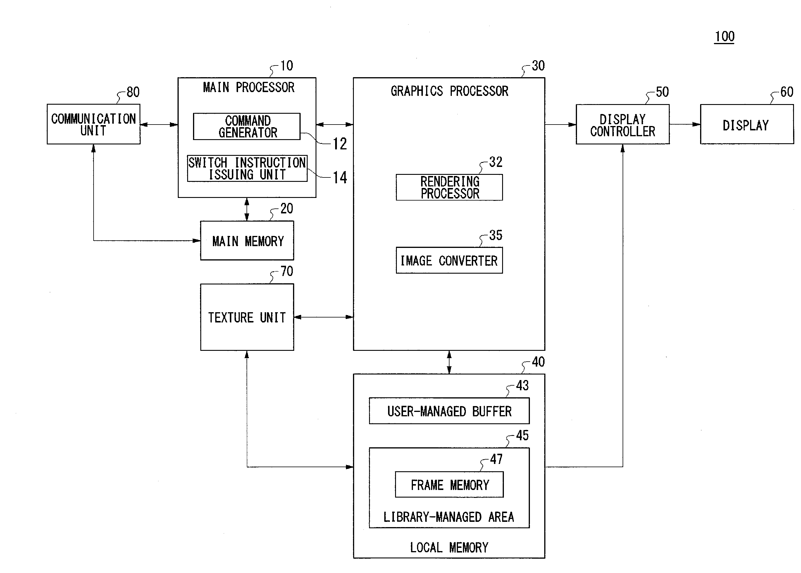
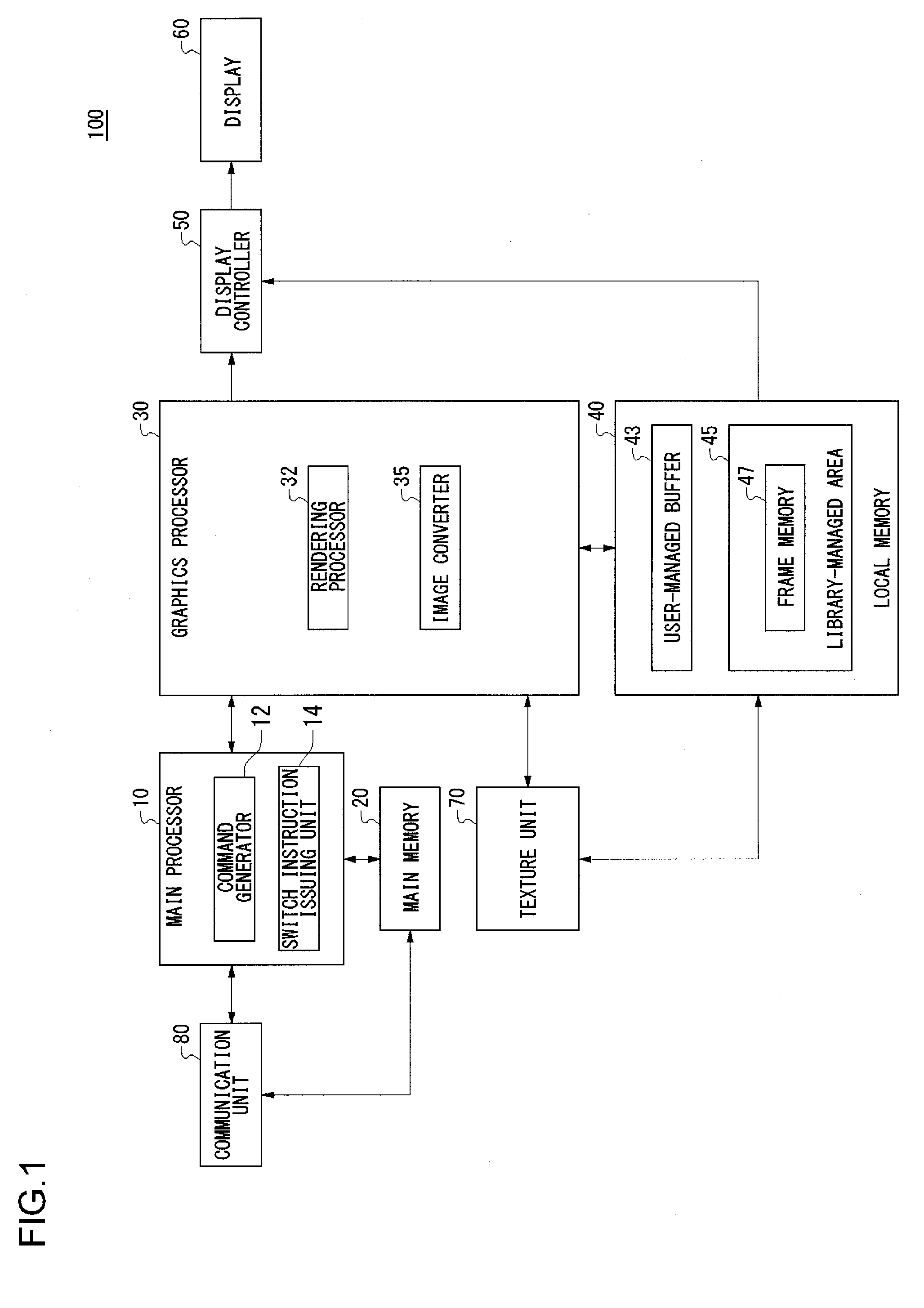
[0030]FIG. 1 shows the structure of a rendering apparatus 100 according to an embodiment. A rendering apparatus 100 performs a rendering process to generate rendering data to be displayed on a screen, based on 3D model information of an object to be rendered (hereinafter, simply referred to as an “object”). The figure depicts a block diagram highlighting the functions. These functional blocks can be realized in various forms by hardware only, software only, or a combination thereof.

[0031]The rendering apparatus 100 includes a main processor 10, a main memory 20, a graphics processor 30, a local memory 40, a display controller 50, a display 60, a texture unit 70, and a communication unit 80. These components are connected to a bus (not shown).

[0032]The main memory 20 is a storage area primarily used by th...


PUM


Abstract

An image converter converts an image rendered at a given vertical synchronous frequency into an image compatible with the specification of a display. A frame memory holds the image converted by the image converter by switching a plurality of buffers. A display controller selects one of the buffers in accordance with the vertical synchronous frequency of the display, and scans out the image from the frame memory accordingly. A switch instruction issuing unit issues a frame buffer switch instruction for designating a frame buffer to scan out from subsequently, in synchronization with the vertical synchronous frequency of the display, instead of immediately after the execution of an image converting process by the image converter.

Description

CROSS REFERENCE TO RELATED APPLICATION[0001]The present application claims priority from Japanese Application No. JP2007-032717, filed Feb. 13, 2007, the disclosure of which is hereby incorporated by reference herein in its entirety.BACKGROUND OF THE INVENTION[0002]1. Field of the Invention[0003]The present invention relates to a rendering technology and, more particularly, to a rendering technology for generating image adapted for a display device.[0004]2. Description of the Related Art[0005]With improvement in the technology for fabricating a thin display such as a liquid crystal display and a plasma display, and the reduction in prices, an extensive variety of display devices are currently available around us. Display devices display high-quality images played back by a DVD player or moving images generated by computer graphics.[0006]In order to display image data output from a computer or a DVD player on a display device, a display controller is necessary which converts an image...

Claims


Application Information

Patent Timeline
IPC IPC(8): G09G5/12
CPCG06F3/14G09G5/363G09G5/391G09G5/399G09G2360/18G09G2340/0414G09G2340/0421G09G2360/02G09G2340/04
Inventor OGISO, TORU
Owner SONY COMPUTER ENTERTAINMENT INC
Why Eureka
Try Eureka