Method For Protecion Switching

Inactive Publication Date: 2008-08-14
NOKIA SIEMENS NETWORKS GMBH & CO KG
View PDF2 Cites 11 Cited by
  • Summary
  • Abstract
  • Description
  • Claims
  • Application Information

AI Technical Summary

Benefits of technology

[0007]The present invention provides a method which leads to a faster and simpler protection switching.
[0008]The present invention provides a simpler method by

Problems solved by technology

However, if Ethernet technology or a similar technology is chosen for data transmission such a topology

Method used


Image

  • Method For Protecion Switching
  • Method For Protecion Switching
  • Method For Protecion Switching

Examples


Embodiment Construction

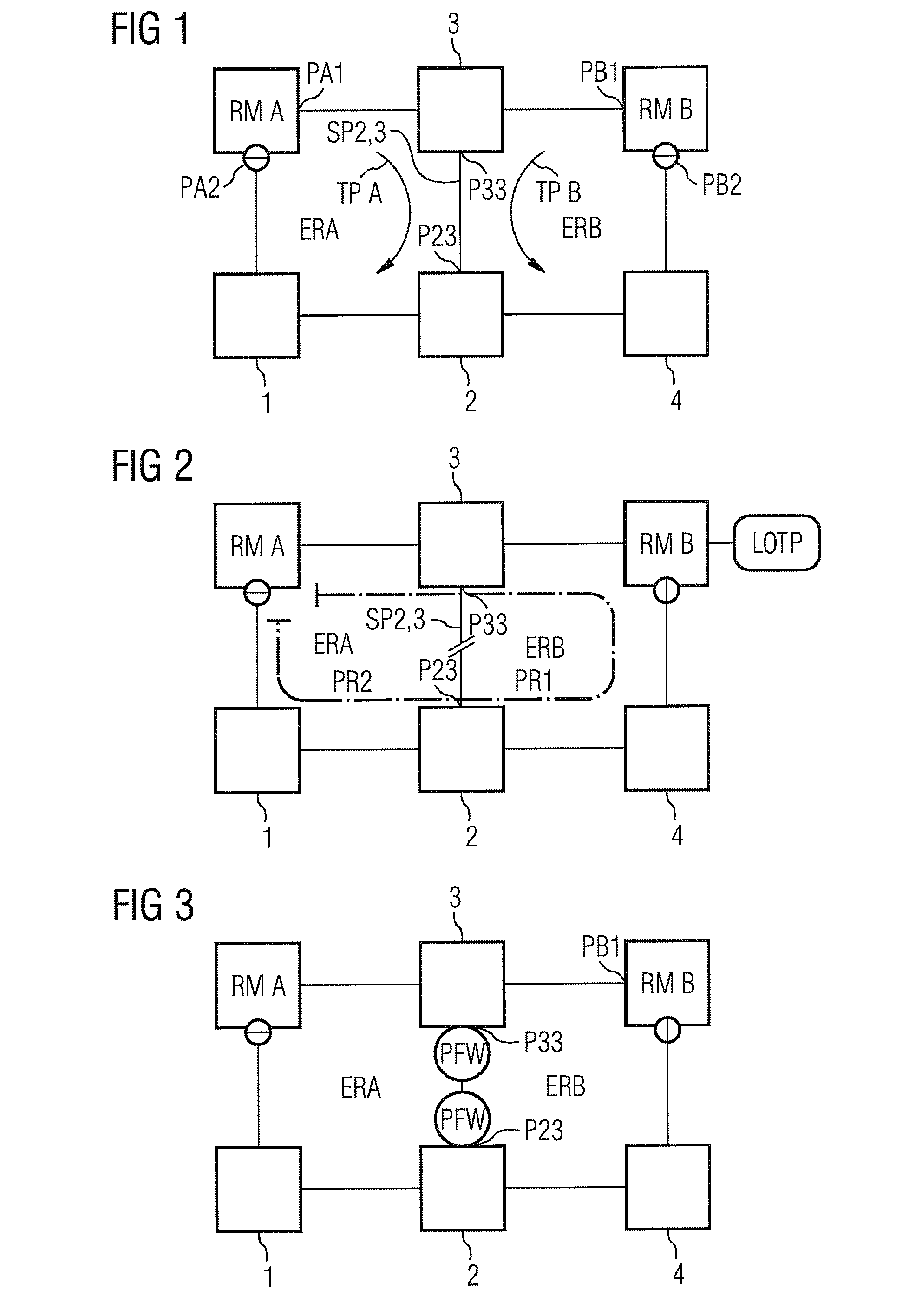
[0015]FIG. 1 shows a network having two rings. A first ring ERA with nodes 1, 2, 3 including an associated ring manager RMA, and a second ring ERB with nodes 2, 3, 4 including an associated ring manager RMB having a higher priority PR1 than the ring manager RMA with priority PR2. Each port of a ring manager or a node can transmit and receive dates. Both rings ERA and ERB share the span SP2,3 between the “common span nodes”2 and 3 (a common span node is a node, which has at least a port P33, P23 connected to the common span, or is exceptionally inserted between these “end nodes” of the common span). According to the Ethernet requirements each ring manager RMA, RMB blocks one of its ports, e.g. PA2 and PB2, so there is no connection between the ports PA1 and PA2 or PB1 and PB2, which are shown on different sides of the ring managers in the drawing, and therefore (data) loops are avoided.

[0016]Each ring manager supervises its associated ring. Ring manager RMA supervises Ring ERA by sen...


PUM


Abstract

The invention relates to a method for protection switching in a data network network including at least two rings (ERA, ERB) with a shared span (SP2,3) and a plurality of nodes (1-4). Each ring (ERA, ERB) has an associated ring manager (RMA, RMB) for checking its associated ring (ERA, ERB) and the ring managers (RMA, RMB) have dedicated different priorities (PR1, PR2). When a failure (interruption) occurs in a shared span, a shared span node (2, 3) sends a failure message (FSP2,3) to a ring manager (RMB) of higher priority (PR1) of an associated ring (ERB), and the ring manager (ERB) unblocks its port (PB2) while the ring manager (RMA) of lower priority (PR1) maintains its port (PA2) blocked.

Description

CLAIM FOR PRIORITY[0001]This application is a national stage application of PCT / EP2006 / 062537 filed on May 23, 2006, which claims the benefit of prior to EP 05011736 filed on May 31, 2005, the contents of which are hereby incorporated by reference.TECHNICAL FIELD OF THE INVENTION[0002]The invention relates to a method for protection switching in a data network.BACKGROUND OF THE INVENTION[0003]Data networks including a plurality of data rings share certain ring spans to enable protection switching and, therefore, prevent single points of failures. However, if Ethernet technology or a similar technology is chosen for data transmission such a topology creates additional problems, because it is necessary to prevent the formation of loops in the network.[0004]The principle of the Ethernet ring protection mechanism ERP is described in U.S. Pat. No. 6,430,151. A redundancy manager, which is connected to the line ends of a ring containing a plurality of nodes, checks the network by transmit...

Claims


Application Information

Patent Timeline
IPC IPC(8): H04L12/437
CPCH04L12/437H04L41/0659H04L12/4637
Inventor DE FRIAS REBELO NUNES, PEDRO RICARDO
Owner NOKIA SIEMENS NETWORKS GMBH & CO KG
Why Eureka
Try Eureka