Radio communication apparatus and radio communication method

a radio communication and radio communication technology, applied in the field of radio communication apparatus and radio communication method, can solve the problems of waste of bss frequency resources and waste of transmission power at the transmission terminal

Active Publication Date: 2008-08-14
PALMIRA WIRELESS AG
View PDF15 Cites 161 Cited by
  • Summary
  • Abstract
  • Description
  • Claims
  • Application Information

AI Technical Summary

Problems solved by technology

However, if the other terminals decide the transmission channel width on the basis of the recommended channel width frame transmitted in accordance with the terminal capability, under the environment in which the other system or BSS of the wireless LAN exists on the extension channel, the other terminals may transmit 40 MHz frame to the terminal even in a channel state which the terminal cannot receive the 40 MHz frame because of interference.
Thus, a problem, such that the frequency resource of the BSS is wasted and a transmission terminal wastes transmission power, is caused.

Method used


Image

  • Radio communication apparatus and radio communication method
  • Radio communication apparatus and radio communication method
  • Radio communication apparatus and radio communication method

Examples


first embodiment

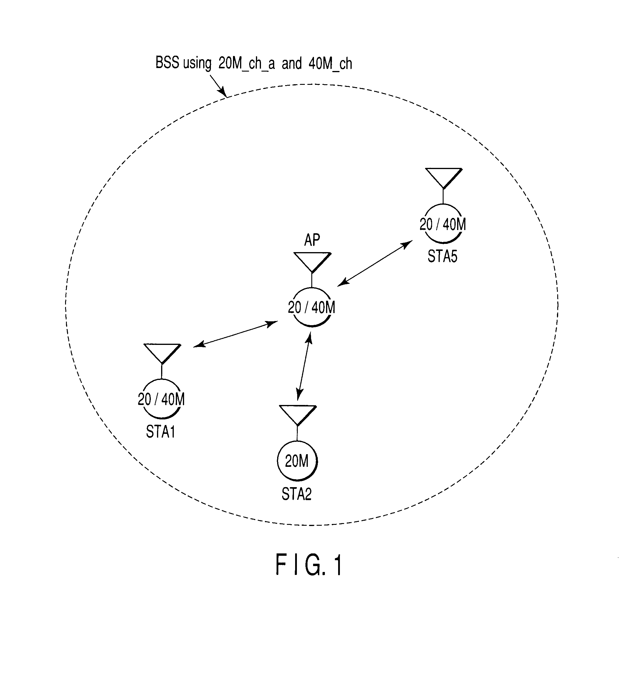
[0027]FIG. 1 shows an example of a radio communication system regarding the first embodiment of the invention. Here, three radio terminals (STA1, STA2, and STA5) are connected to one access point (AP) which forms one basic service set (BSS). The AP intensively manages the BSS.

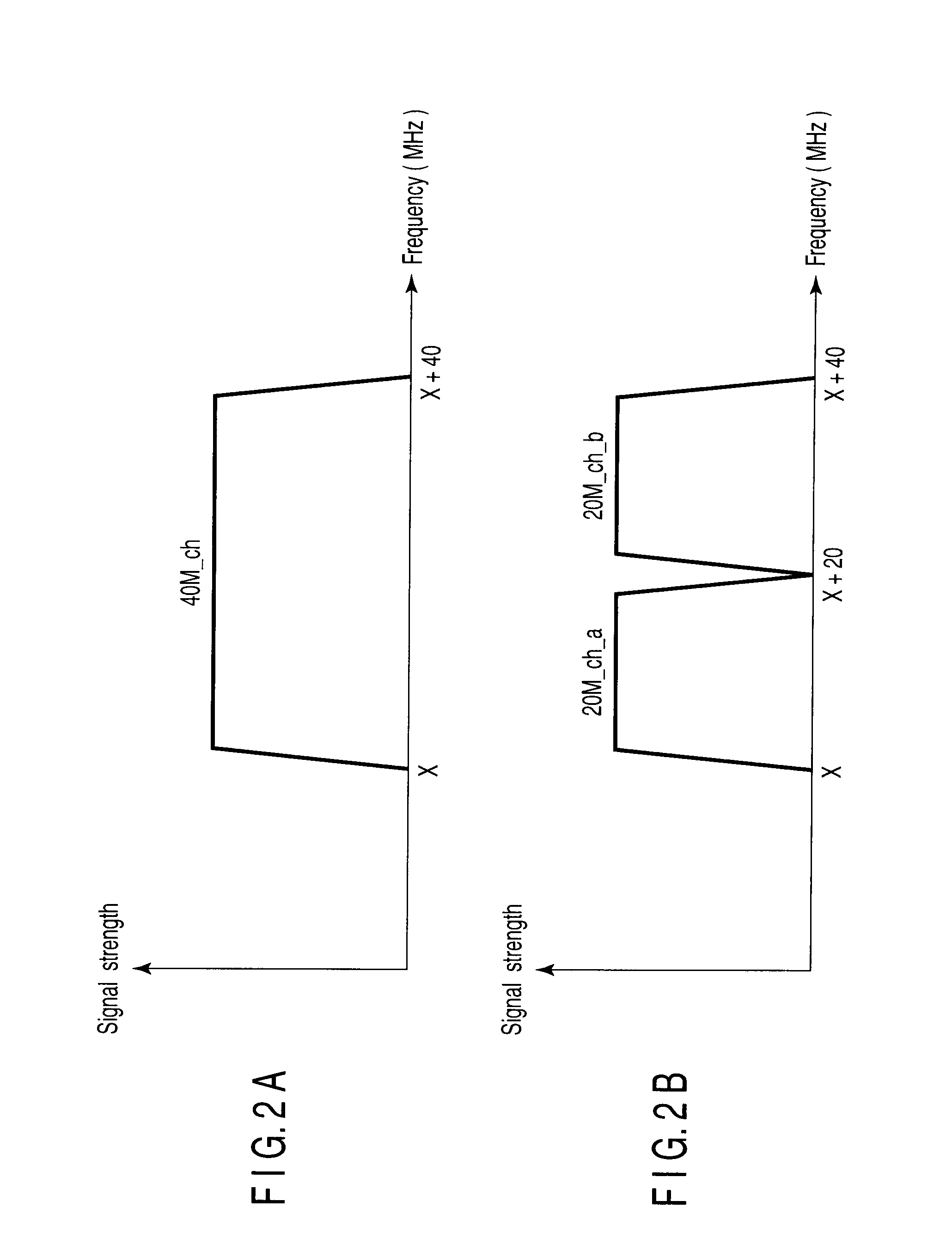
[0028]Within the BSS, the system uses two kinds of channels differing in frequency channel width to transmit and receive frames. The two kinds of channels are namely a first channel, with a first communication channel width, and a second channel, with a second communication channel width. In the first embodiment, the first communication channel width is set to 20 MHz and the second communication channel width is set to 40 MHz.

[0029]The AP, the STA1 and the STA5 in FIG. 1 correspond to the channel widths of both the 20 MHz and 40 MHz, and these terminals may transmit and receive the frames by using either a channel 40M_ch or a channel 20M_ch_a. The STA2 is a terminal corresponding only to the channel width of 20...

second embodiment

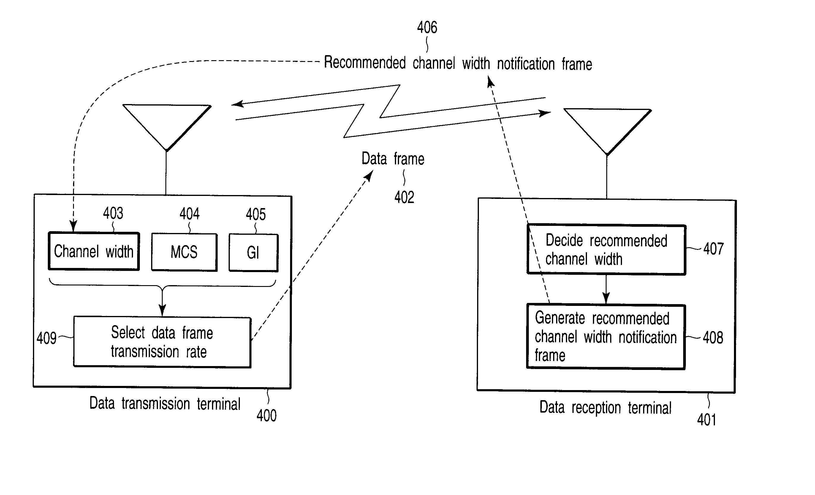
[0064]While the aforementioned first embodiment has described the example of notifying the recommended channel width by using the recommended channel width notification frame, the second embodiment will describe an example of notifying the recommended channel width by using a ‘recommended transmission channel width field’ (hereinafter referred to as a ‘recommended channel width notification field’ of a management frame.

[0065]The system configurations, channel arrangements, frame transmission systems, aspects of frame error occurrences, configurations of radio communication apparatuses, etc., shown from FIG. 1 to FIG. 9 apply similarly to the second embodiment.

[0066]As mentioned in the first embodiment, in the self-BSS of FIG. 3, when transmitting a data frame, the AP, STA1 and STA5 decide the transmission channel width in accordance with the recommended channel width of the destination terminal. Each terminal notifies the recommended channel width to other terminals other than the s...

third embodiment

[0074]While the foregoing first embodiment has described the example of transmitting the recommended channel width notification frame on the basis of the presence or absence of interference on the extension channel estimated from the frame error rate of the frame in the third channel width mode ‘Duplicate’ and the frame error rate of the 40 MHz reception frame, in the third embodiment, an example of comparing the transmission channel width of a frame so as to transmit from a self-terminal to a destination terminal with a reception channel width of a frame to be transmitted from the destination terminal to the self-terminal, and transmitting a recommended channel width notification frame on the basis of the comparison result will be described.

[0075]The system configurations and channel arrangements depicted in FIGS. 1 to 4 given in the first embodiment apply similarly to the third embodiment.

[0076]FIG. 10 shows a block diagram of a radio communication apparatus regarding the third em...


PUM


Abstract

A radio communication apparatus that performs first radio communication using a first channel among two first channels each having a first channel width, and second radio communication using a second channel having a second channel width that is wider than the first channel width and also having a channel width overlapping with the two first channels. The apparatus includes an interference detection device which detects that interference occurs in the first channel among the two first channels, and a frame generation unit which generates a notification frame that recommends the use of only the first channel width. An instruction unit instructs the frame generation unit to generate the notification frame when the occurrence of interference is detected by the interference detection device. A frame transmission unit transmits the notification frame generated from the frame generation unit in response to the instruction from the instruction unit.

Description

CROSS-REFERENCE TO RELATED APPLICATIONS[0001]This application is based upon and claims the benefit of priority from prior Japanese Patent Application No. 2007-029400, filed Feb. 8, 2007, the entire contents of which are incorporated herein by reference.BACKGROUND OF THE INVENTION[0002]1. Field of the Invention[0003]The present invention relates to a radio communication apparatus and a radio communication method for performing media access control on the basis of a carrier sense state.[0004]2. Description of the Related Art[0005]In recent years, wireless local area networks (LANs) have become rapidly and widely used in environments ranging from offices to homes, as well as for hot-spot services in public places. Although standards such as IEEE802.11a, which uses a 5 GHz band, and IEEE802.11b / g, which uses a 2.4 GHz band have become mainstream, IEEE802.11e, which extends the Quality of Service (QoS) function to a medium access control (MAC) layer on IEEE802.11a / b / g has also been estab...

Claims


Application Information

Patent Timeline
Patent Type & Authority Applications(United States)
IPC IPC(8): H04J1/16H04W28/20H04W72/08
CPCH04B7/2656H04W72/082H04W28/20H04W72/541
Inventor UTSUNOMIYA, YORIKOADACHI, TOMOKOTAKAGI, MASAHIRO
Owner PALMIRA WIRELESS AG
Why Eureka
Try Eureka