Method for controlling color-image forming apparatus

Active Publication Date: 2008-08-14
HEWLETT PACKARD DEV CO LP
View PDF10 Cites 0 Cited by
  • Summary
  • Abstract
  • Description
  • Claims
  • Application Information

AI Technical Summary

Benefits of technology

[0010]Several aspects and example embodiments of the present invention provide a method of controlling a color image forming apparatus to reduce an image distortion at the boundary of a composite black text resulting from a mis-registration, thereby increasing the quality of a printed image.
[0015]According to another aspect of the present invention, there is provided a color image forming apparatus that prints a composite black text using cyan (C), magenta (M), yellow (Y), and black (K) channels, the apparatus including: a control unit to search for a boundary area in print data if the print data is determined to correspond to a composite black text, to reduce the C channel, the M channel, and the Y channel at the boundary area, and to compensate for the K channel by a density of the reduced C, M, and Y channels.

Problems solved by technology

In this case, the color image forming apparatus has difficulty in correctly printing individual colors at desired positions due to a variety of factors resulting from printing a variety of colors on a single print medium.
Particularly, color distortion by which color dots disperse in all directions becomes serious at a boundary between composite black texts due to the mis-registration.
In other words, the C, M, Y, and K dots may be printed in the wrong locations due to mechanical errors resulting in the dispersion of the color dots.
Accordingly, the desired image is distorted by the mis-registration, resulting in a deterioration of the printed image quality.

Method used


Image

  • Method for controlling color-image forming apparatus
  • Method for controlling color-image forming apparatus
  • Method for controlling color-image forming apparatus

Examples


Embodiment Construction

[0025]Reference will now be made in detail to the present embodiments of the present invention, examples of which are illustrated in the accompanying drawings, wherein like reference numerals refer to the like elements throughout. The embodiments are described below in order to explain the present invention by referring to the figures.

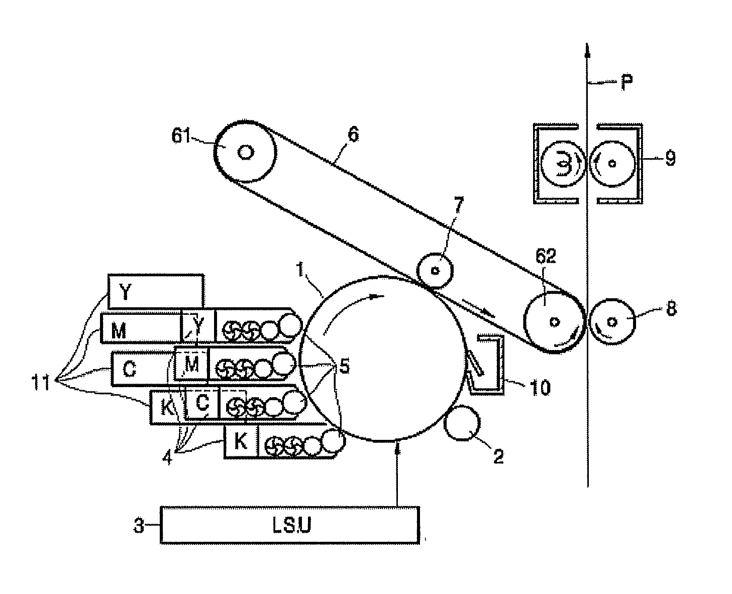
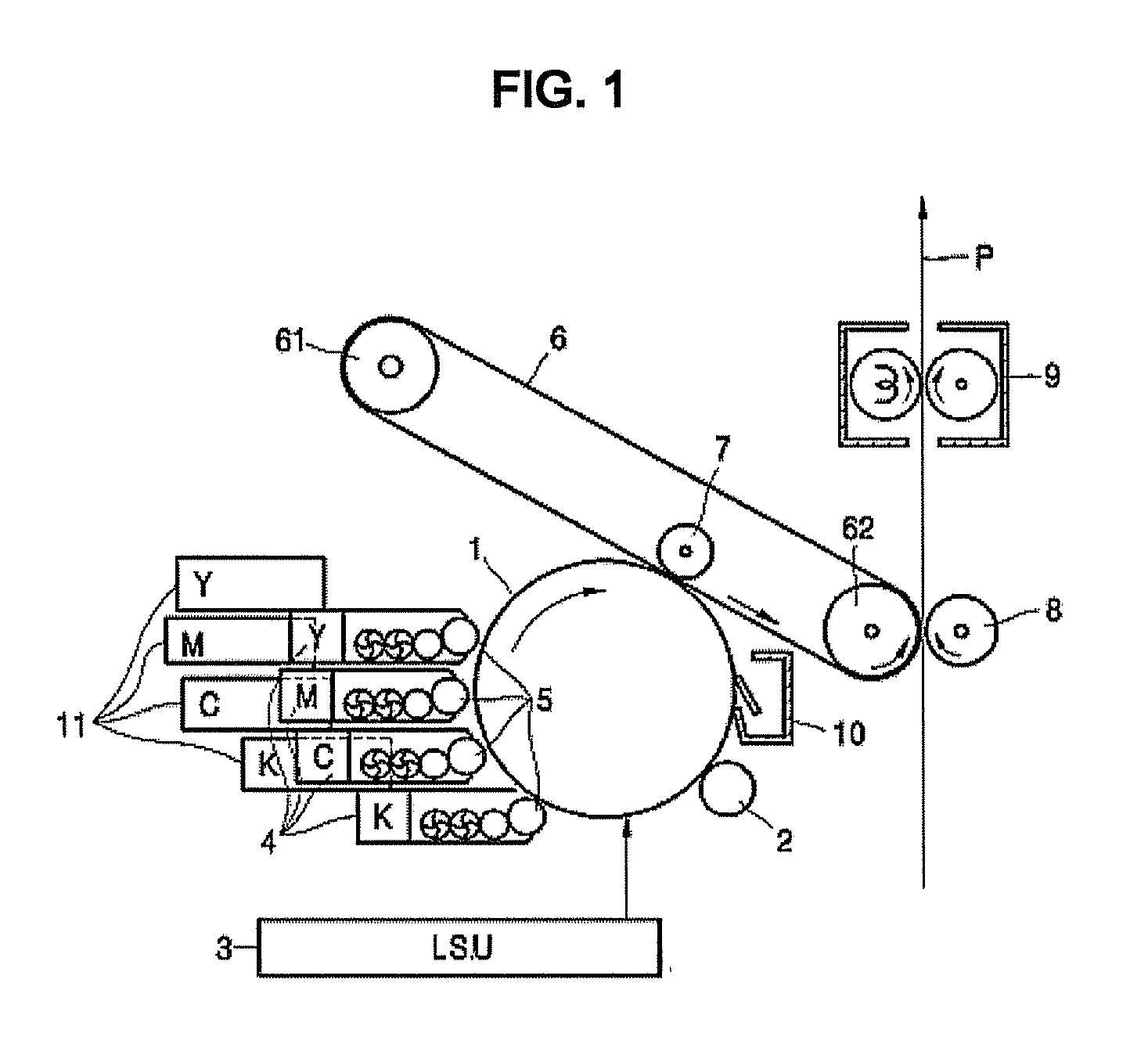
[0026]FIG. 1 is a structural diagram illustrating an image forming apparatus according to an example embodiment of the present invention. Referring to FIG. 1, the color image forming apparatus includes a photoconductive drum 1, a charged roller 2, an exposure unit 3, a developing cartridge 4, an intermediate transfer belt 6, a first transfer roller 7, a second transfer roller 8, and a fixing unit 9.

[0027]The photoconductive drum 1 is configured such that a photoconductive layer is formed at a circumference of a cylindrical metal drum thereof. It is understood that a photoconductive belt (not shown) may be used instead of the photoconductive drum 1. The...


PUM


Abstract

A method of controlling a color image forming apparatus, the method including: reducing the C, M, and Y channels from the boundary area of the composite black text, thereby allowing only the K channel to be left on the outermost boundary of the composite black text; and compensating for the K channel by the density of the reduced C, M, and Y areas, so that image distortion generated at the boundary of the composite black text is compensated for, resulting in increased image quality of the printed image of the composite black text.

Description

CROSS-REFERENCE TO RELATED APPLICATION[0001]This application claims all benefits accruing under 35 U.S.C. §119 from Korean Patent Application No. 2007-13211, filed on Feb. 8, 2007 in the Korean Intellectual Property Office, the disclosure of which is incorporated herein by reference.BACKGROUND OF THE INVENTION[0002]1. Field of the Invention[0003]Aspects of the present invention relate to a method of controlling a color image forming apparatus, and more particularly to a method of controlling a color image forming apparatus to compensate for an output image distortion caused by mis-registration during the printing operation of a color document.[0004]2. Description of the Related Art[0005]Generally, an image forming apparatus converts an image file (such as a user's document created by an application program or an image captured by a user's digital camera) into encoded data, and prints the encoded data on a print medium (such as paper) so that the user can view the image. Examples of ...

Claims


Application Information

Patent Timeline
IPC IPC(8): G03G15/01
CPCG03G15/01G03G2215/0158H04N1/6022H04N1/4092H04N1/58G03G2215/047G03G15/00
Inventor SHIN, SANG YOUN
Owner HEWLETT PACKARD DEV CO LP
Why Eureka
Try Eureka