
Remote Control Device

Inactive Publication Date: 2008-08-14
KYOTO UNIV
View PDF13 Cites 34 Cited by
  • Summary
  • Abstract
  • Description
  • Claims
  • Application Information

AI Technical Summary

Benefits of technology

[0005]Moreover, in the method described in Patent Citation 2, the non-contact detection of the motions of the operator's elbow requires that the operator should keep an elbow up. So, the operator's arm may easily become tired. Furthermore, in the arrangement in which the acceleration sensor is attached to the elbow, as described in Non-Patent Citations 1 and 2, the operator's arm may easily become tired, too.
[0014]As described above, in accordance with the remote control device of the present invention, as the elbow switch allows a motion control of at least 2 degrees of freedom, the user can operate targets to control with higher degrees of freedom such as a robot arm or the like. As motions of the user's arm are conveyed to the robot arm by the master arm main body, the user can operate the robot arm as if it is a user's own arm. So, the user can command more various motions to the robot arm. Moreover, the user can intuitively operate the elbow switch with his own elbow, and long-hour control operation of the target to control becomes less fatiguing.

Problems solved by technology

However, in the arrangement in which the robot arm is controlled by the switch provided at a handgrip controller as described in Patent Citation 1, actual actions of the robot arm are vastly different from the operator's action of pressing the switch.
So, an operator cannot intuitively control the robot arm.
So, the operator's arm may easily become tired.
Furthermore, in the arrangement in which the acceleration sensor is attached to the elbow, as described in Non-Patent Citations 1 and 2, the operator's arm may easily become tired, too.
So, it is more difficult for the operator to handle additional switches.
But the device cannot be provided with an armrest where the operator can place an arm.
So, the operator's arm may easily become tired after long-hour control operation.

Method used


Image

  • Remote Control Device
  • Remote Control Device
  • Remote Control Device

Examples


Embodiment Construction

[0034]1. Outline of Master Arm

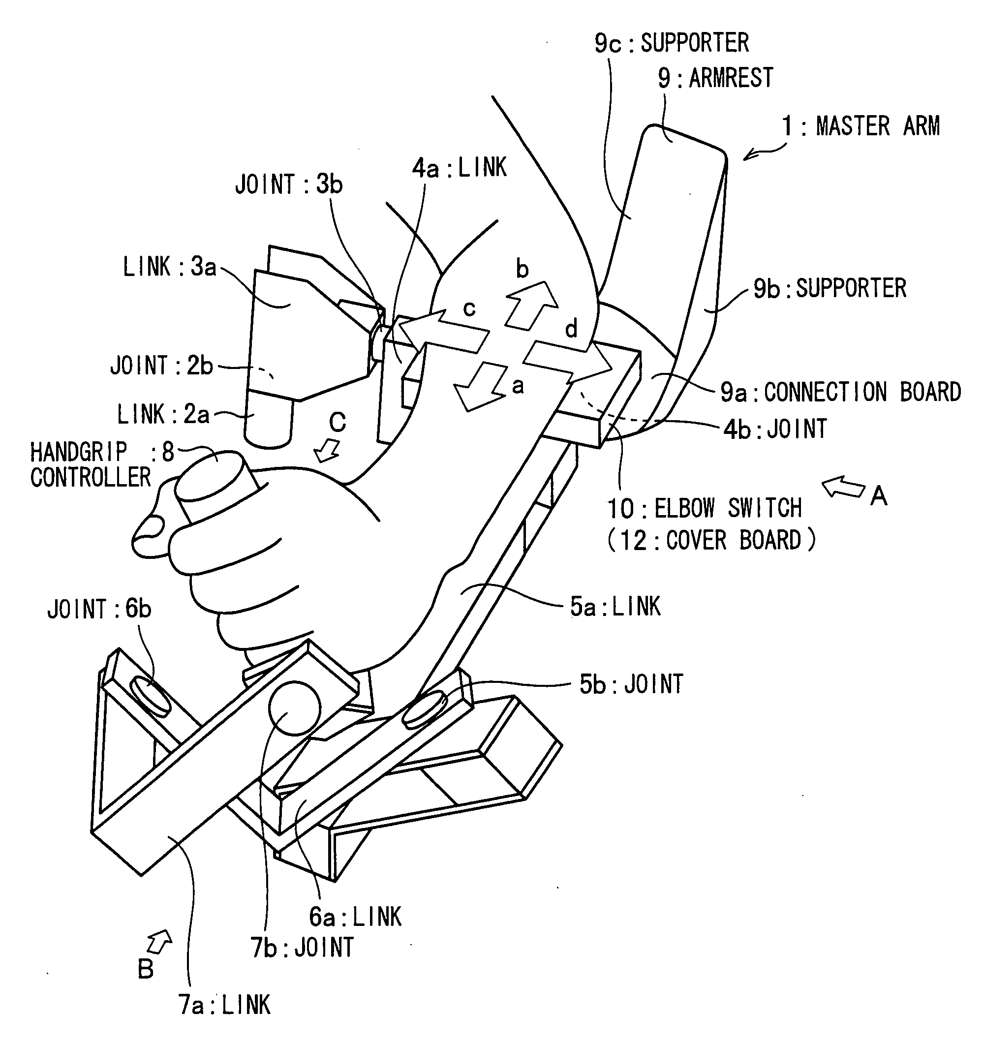
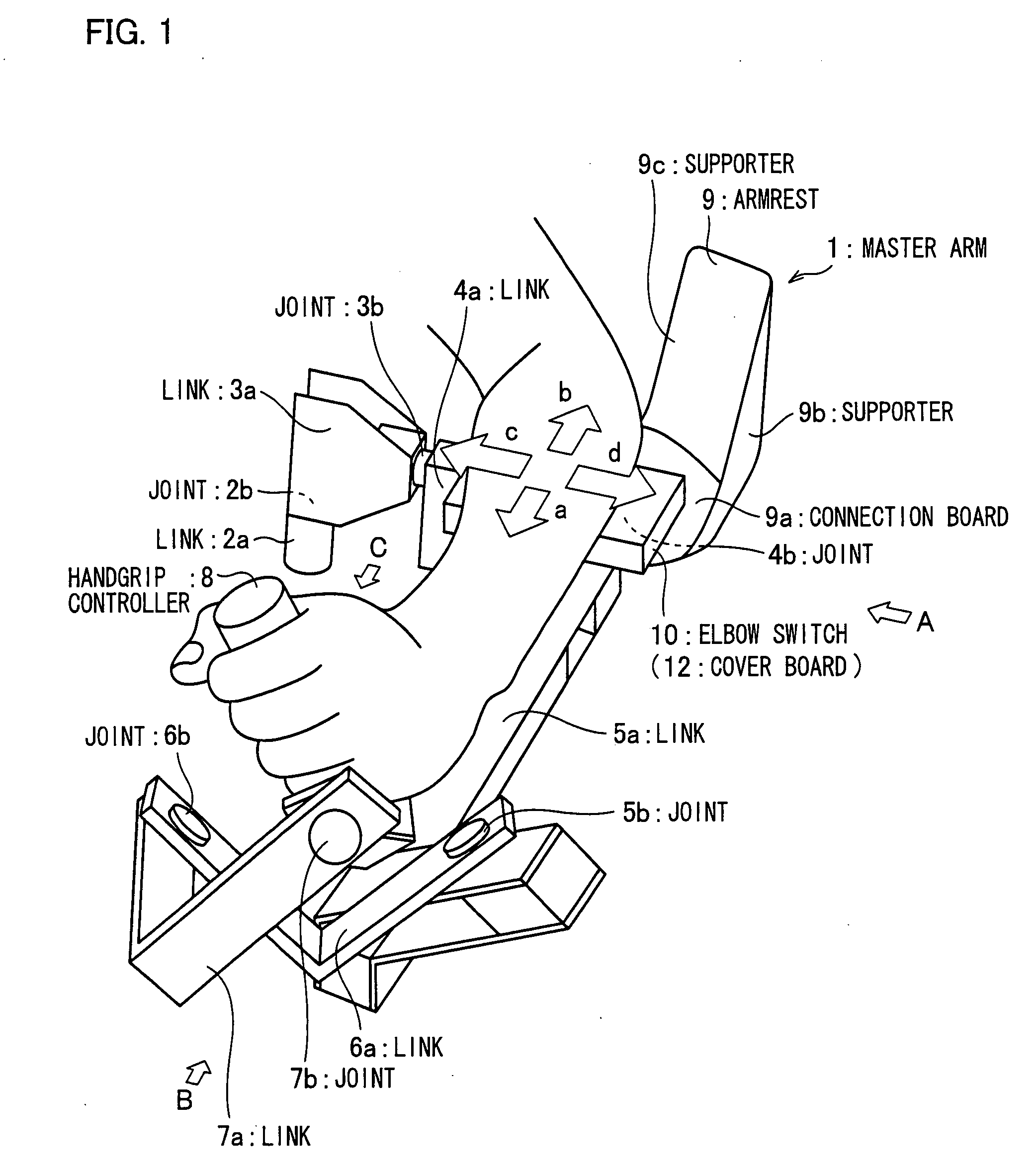
[0035]One embodiment of the present invention is described below. As illustrated in FIG. 1, a master arm 1, which is a remote control device, includes links 2a, 3a, 4a, 5a, 6a, 7a, and a handgrip controller 8. Each of these links 2a through 7a is connected respectively by joints 2b, 3b, 4b, 5b, 6b, and 7b. In addition, an armrest 9 is fixed to the link 5a, and an elbow switch 10 is fixed to the link 4a.

[0036]Thus, the master arm 1 has a configuration that fits with a bone structure of a use's arm by the links 2a through 7a, joints 2b through 7b, and handgrip controller 8 being connected respectively. In claims, a mechanism including the links 2a through 7a, joints 2b through 7b, and handgrip controller 8 is recited as a “master arm main body”.

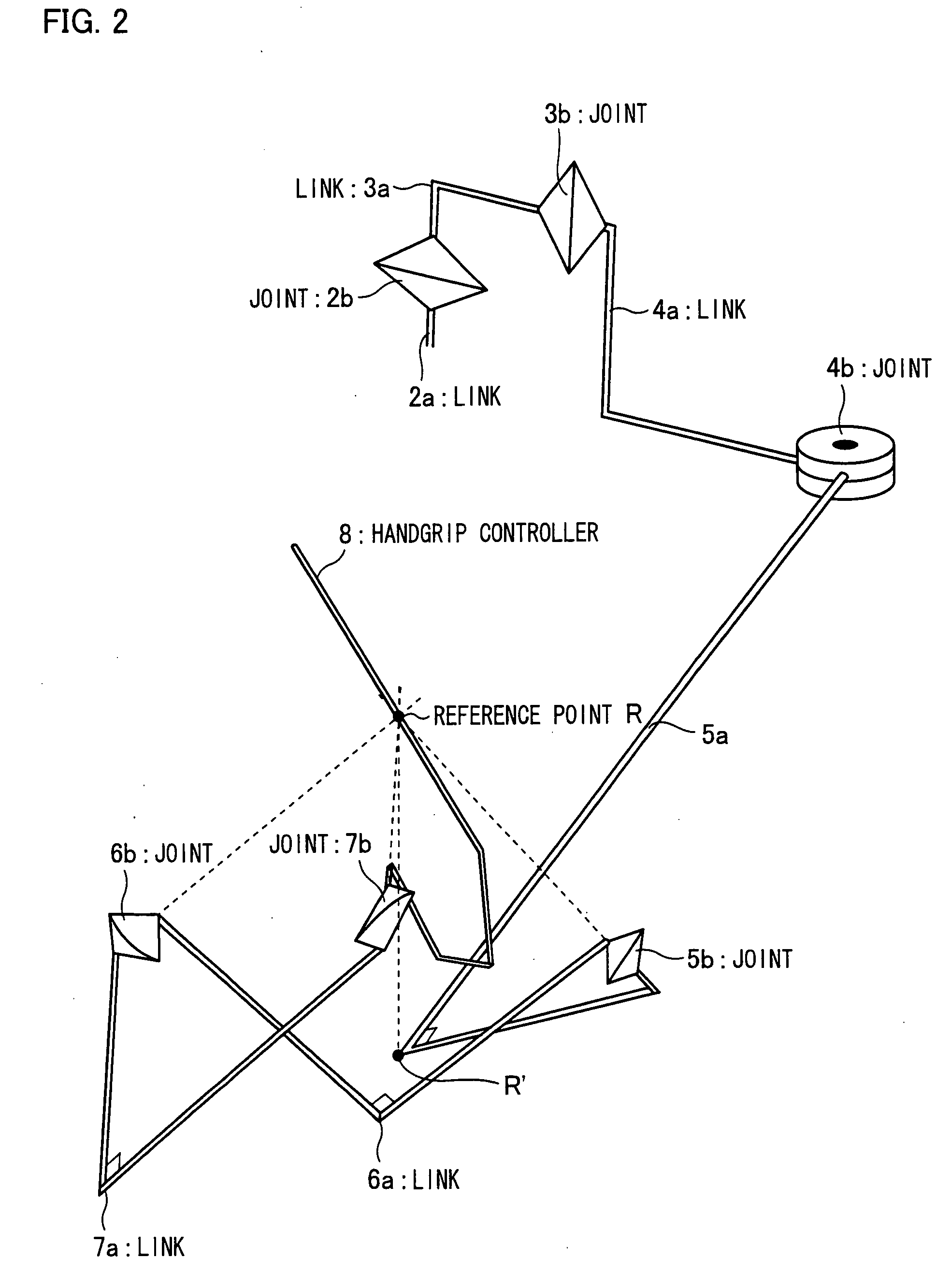
[0037]In FIG. 1, the link 4a, link 5a, joint 2b, and joint 4b are illustrated behind the links and an elbow switch, and it may be incomprehensible in how these components are connected. So, a simplified configurat...


PUM


Abstract

In one embodiment of the present invention, a remote control device is disclosed which enables a user to intuitively operate a target to control such as a robot arm with a little burden, and command various motions to the target. The remote control device includes a master arm main body, joints, and a handgrip controller, and an elbow switch. The master arm main body conveys motions of the user's arm to the robot arm. The elbow switch is provided at a position of the master arm body, on which the user can place his elbow, and has a motion control with 2 degrees of freedom.

Description

TECHNICAL FIELD[0001]The present invention relates to a remote control device for remotely controlling a robot arm.BACKGROUND ART[0002]Generally, movement degree of freedom of a robot arm operated by a remote control device called a master arm is at most 6 degrees of freedom. Therefore, the use of the master arm to control the robot arm faces no problem as long as the robot arm has 6 degrees of freedom or less. However, in order to remotely control a robot arm having redundant degrees of freedom such as a humanoid robot, an additional input unit is required.[0003]Conventionally, a handgrip controller of a remote control device is provided with a switch for controlling a position of an elbow joint of a robot arm (see Patent Citation 1). Also, Patent Citation 2 disclosed that a photoelectronic sensor or a micro linear scale is used for detecting motions of an operator's elbow in a non-contact manner. Moreover, a technique of controlling a robot arm by an acceleration sensor attached t...

Claims


Application Information

Patent Timeline
IPC IPC(8): B25J3/00B25J13/02G05G1/58G05G9/04
CPCB25J13/02G05G2009/04774G05G9/04G05G1/62
Inventor YOKOKOHJI, YASUYOSHISATO, YUJIKAWATA, KOHEISHIRATSUCHI, KOJI
Owner KYOTO UNIV
Learn More