Methods and apparatuses for joining a pumping cartridge to a pump drive

a technology of pump drive and pump cartridge, which is applied in the direction of fluid jet surgical cutters, liquid fuel engines, incision instruments, etc., can solve the problems of relatively frequent replacement and technical challenges of the procedur

Active Publication Date: 2008-08-14
HYDROCISION
View PDF87 Cites 60 Cited by
  • Summary
  • Abstract
  • Description
  • Claims
  • Application Information

AI Technical Summary

Benefits of technology

[0013]In certain embodiments of the first series of embodiments, the selected position is indicated by a detectable position indicator, while in these or other embodiments, after the moving step, a step of using the pumping cartridge in a medical pumping procedure is performed. In certain of these or other embodiments, the pumping cartridge is constructed and arranged to enable it to withstand and generates a pressure of at least about 5,000 p.s.i., without failure or leakage.

Problems solved by technology

Such disposable cartridges may, in certain embodiments, be designed to be used only for a single medical procedure, and thus may require relatively frequent replacement.
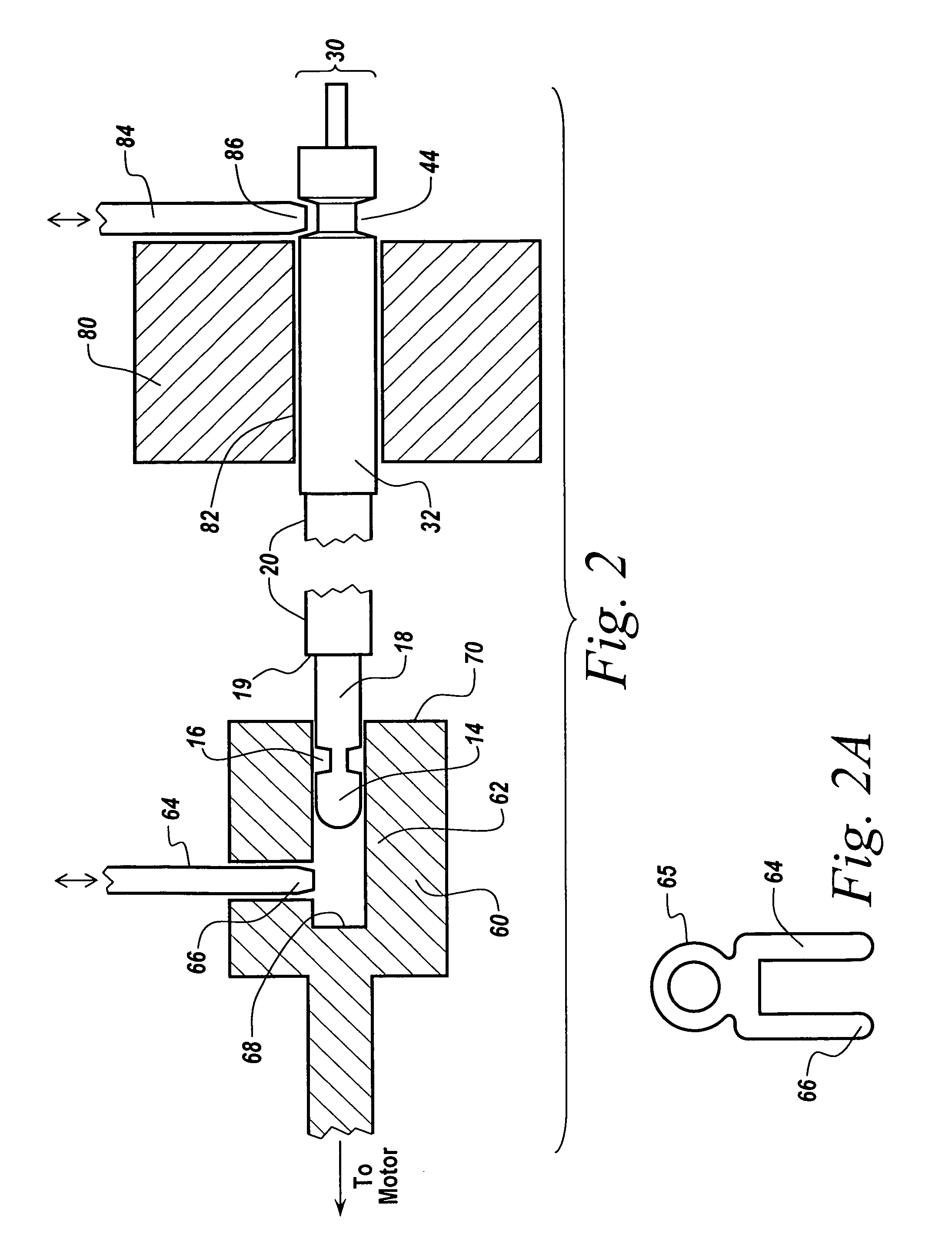
In a medical environment, such as an operating room, there are several constraints that may be desirable to be satisfied in a procedure for coupling a piston to a drive that make such a procedure technically challenging.
First, it may be desirable that the connection can be made without removing the piston from the cylinder, since that would tend to render the pumping zone non-sterile.

Method used


Image

  • Methods and apparatuses for joining a pumping cartridge to a pump drive
  • Methods and apparatuses for joining a pumping cartridge to a pump drive
  • Methods and apparatuses for joining a pumping cartridge to a pump drive

Examples


Embodiment Construction

[0023]To more clearly illustrate certain aspects of the invention, a particular, exemplary embodiment is described below. Numerous variations are possible that encompass the same invention, and the invention is limited only by the claims appended hereto, and is not limited to the exemplary configurations and dimensions set forth in this detailed description.

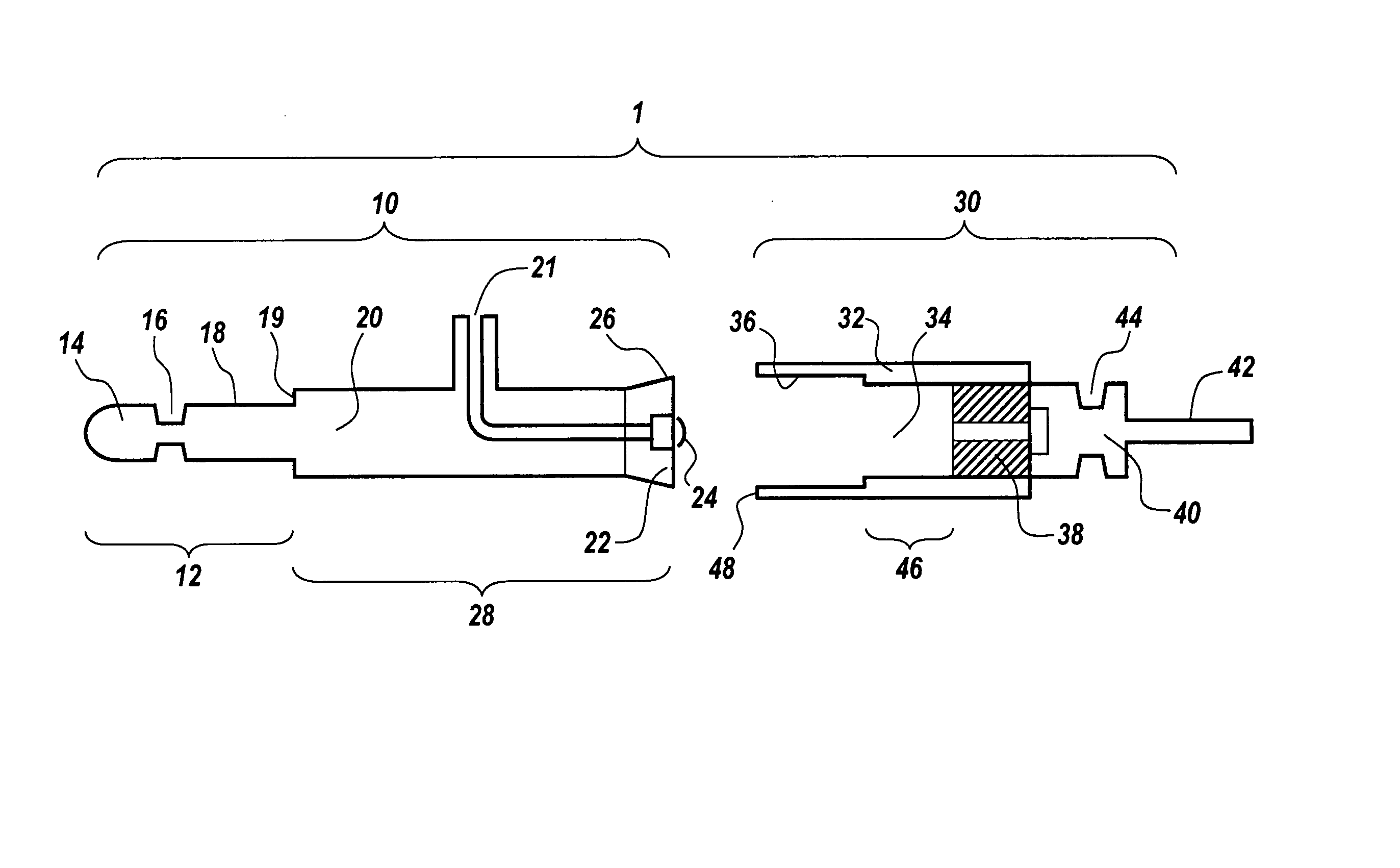
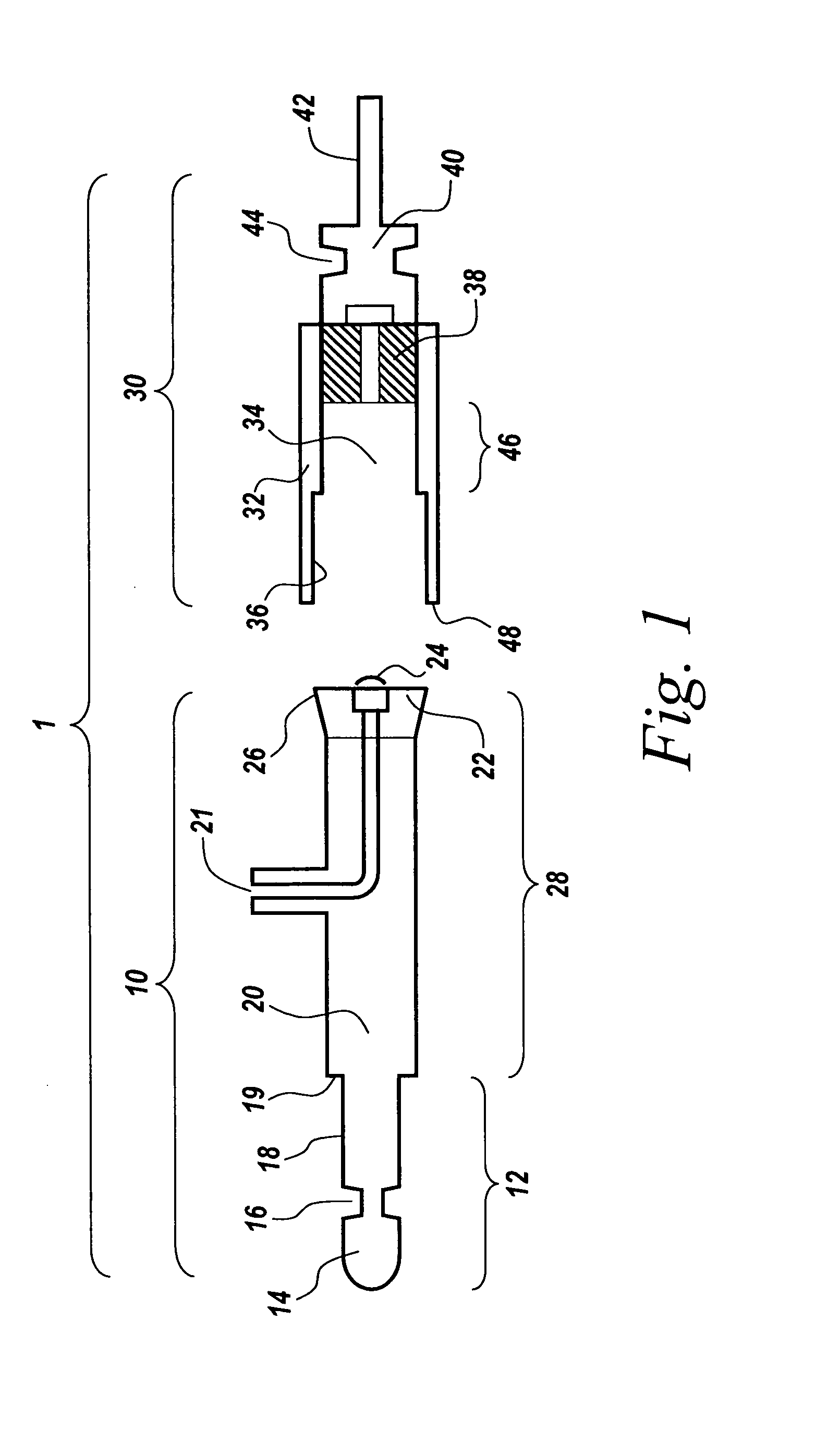
[0024]FIG. 1 is a schematic illustration showing a pumping cartridge assembly, according to an embodiment of the invention, generally labeled 1. The cartridge, in this embodiment, has two parts, a piston assembly 10 and a cylinder assembly 30. The piston assembly 10 has a connecting region 12 and a body region 28. The connecting region 12 comprises a terminal knob 14, a groove 16, and a shaft 18 meeting body 20 at lip 19. Body region 28 has a body 20, a fluid inlet 21 connecting with a check valve 24 (the structure of which is described in greater detail in US 2002 / 0176788-A1); and a piston 22 carried on body 20 and having a seal...


PUM

PropertyMeasurementUnit
diameteraaaaaaaaaa
stroke lengthaaaaaaaaaa
distanceaaaaaaaaaa

Abstract

Apparatus and methods of their use are described for engaging a pumping cartridge with a pump drive. In certain embodiments, the cartridge, comprising a cylinder and a movable piston assembly, is initially assembled or subsequently positioned so that the distance between the attachment point on the piston assembly for coupling to a drive assembly, and a reference point on the cylinder, is greater than the maximal distance that will be encountered during normal oscillation of the piston during use. The cartridge, in certain embodiments may be pressed into a drive assembly having means for immobilizing the cartridge and means for coupling the piston assembly to the driveshaft. In certain embodiments, when the cartridge is fully inserted into the drive assembly, the piston is pressed into the cylinder sufficiently to establish a selected distance so that the piston shaft is in the proper position to engage with a coupling mechanism carried on the driveshaft.

Description

RELATED APPLICATIONS[0001]This non-provisional application claims the benefit under Title 35, U.S.C. §119(e) of co-pending U.S. Provisional Application Ser. No. 60 / 440,123, filed, Jan. 15, 2003, which is incorporated herein by reference. This application is a continuation-in-part of U.S. application Ser. No. ______ (not yet assigned), filed Jan. 9, 2004 under Attorney Docket No. S1192.70030US01, titled: HIGH PRESSURE PUMPING CARTRIDGES FOR MEDICAL AND SURGICAL PUMPING AND INFUSION APPLICATIONS, by: Timothy E. Moutafis and David M. Fischer, now pending; which is a continuation of U.S. application Ser. No. 10 / 134,970, filed Apr. 29, 2002, now abandoned; which claims priority to U.S. Provisional Application Ser. No. 60 / 287,219, filed Apr. 27, 2001, each of which is incorporated herein by reference.BACKGROUND[0002]1. Field of the Invention[0003]The invention relates generally to pumping systems employing pumping cartridges that can be disengaged from a pump drive unit, and, more specifi...

Claims


Application Information

Patent Timeline
Patent Type & Authority Applications(United States)
IPC IPC(8): A61M5/315A61B17/3211A61B17/32A61M5/142F04B53/12F04B53/14
CPCF04B53/143F04B53/122Y10T29/49236F04B53/121F04B53/147A61B17/3203
Inventor MOUTAFIS, TIMOTHY E.BROMANDER, EDWARD J.
Owner HYDROCISION
Why Eureka
Try Eureka