
Protecting device for unmanned aerial vehicle falling preventing

A protection device and fuselage technology, which is applied to aircraft indicating devices, unmanned aerial vehicles, gyrocopters, etc., can solve the problems of limited buffering effect of protective rods, insufficient fuselage protection effect, and shortened service life of the device, so as to reduce the The effect of small impact force, reducing speed and increasing wind resistance

Inactive Publication Date: 2019-03-01
易蕾
View PDF1 Cites 12 Cited by
  • Summary
  • Abstract
  • Description
  • Claims
  • Application Information

AI Technical Summary

Problems solved by technology

In this device, the UAV is protected by the buffering effect of the protective bar, the sponge pad and the spring, and the impact force on the UAV body is reduced when the UAV falls. Larger, directly falling to the ground will produce a huge impact force, the buffer effect of the protective rod, sponge pad and spring is limited, and the protection effect on the fuselage is insufficient, and the protective rod is easily damaged by a strong impact, which reduces the use of the device life

Method used


Image

  • Protecting device for unmanned aerial vehicle falling preventing
  • Protecting device for unmanned aerial vehicle falling preventing
  • Protecting device for unmanned aerial vehicle falling preventing

Examples


Embodiment Construction

[0022] The following will clearly and completely describe the technical solutions in the embodiments of the present invention with reference to the accompanying drawings in the embodiments of the present invention. Obviously, the described embodiments are only some, not all, embodiments of the present invention.

[0023] In describing the present invention, it should be understood that the terms "upper", "lower", "front", "rear", "left", "right", "top", "bottom", "inner", " The orientation or positional relationship indicated by "outside", etc. is based on the orientation or positional relationship shown in the drawings, and is only for the convenience of describing the present invention and simplifying the description, rather than indicating or implying that the referred device or element must have a specific orientation, so as to Specific orientation configurations and operations, therefore, are not to be construed as limitations on the invention.

[0024] refer to Figure ...


PUM


Abstract

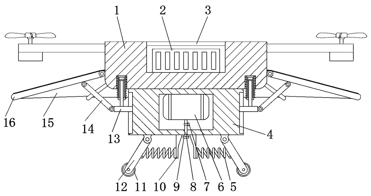
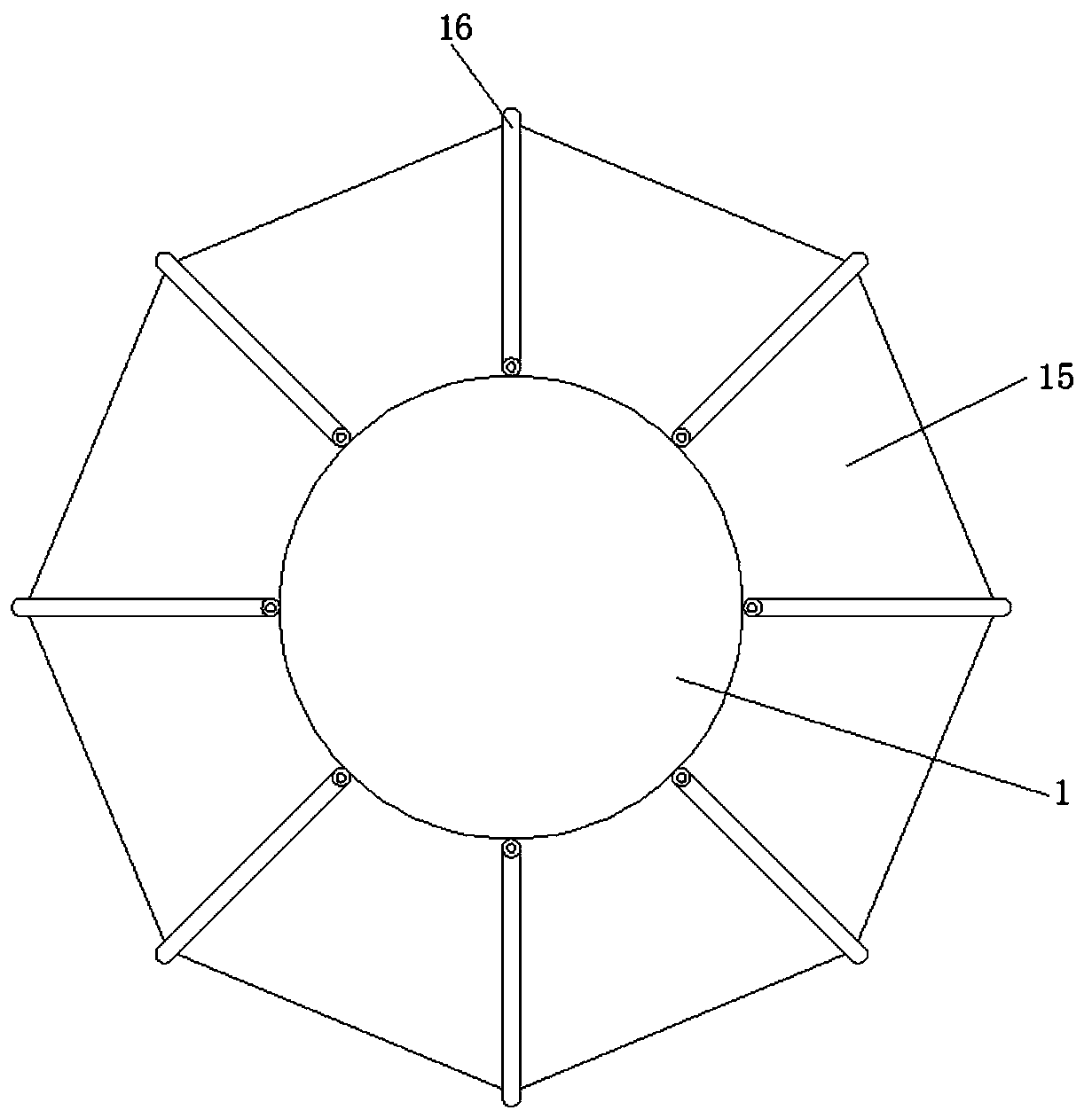
The invention discloses a protecting device for unmanned aerial vehicle falling preventing. The protecting device comprises a device body; a fixing box is welded to the outer wall of the bottom of thedevice body, and a sliding ring sliding groove is formed in the outer wall of one side of the fixing box; a sliding ring is slidably connected to the inner wall of the sliding ring sliding groove, and a connecting rod is connected to the outer wall of the sliding ring through hinges; the outer wall of one end of the connecting rod and the outer wall of one side of the device body are connected with the same rotating rod through hinges, and the same wind resisting cloth is fixed to the outer wall of the top of the rotating rod and the outer wall of one side of the device body through screws; and a mounting groove is formed in the outer wall of the bottom of the device body, and a magnetic conductive column is welded to the inner wall of the mounting groove. Wind resistance borne by the device body during falling can be increased, the falling speed and acceleration of the device body are decreased advantageously, collision force generated when the device body falls and then makes contact with the ground is decreased advantageously, reverse impact force borne by the device body is decreased through the elastic buffering effect of two damping springs, and thus the protective effect onthe device body is improved advantageously.

Description

technical field [0001] The invention relates to the technical field of drones, in particular to a protective device for preventing falling of drones. Background technique [0002] UAVs are widely used in aerial photography, agriculture, express transportation, disaster rescue and other fields. If the UAV fails and the UAV falls, the parts on the UAV will be damaged by strong impact. If there is no anti-fall protection, it will cause to serious economic losses. [0003] After searching, the Chinese Patent Publication No. is CN207374688U, which discloses a UAV fall protection device, including a protective bar, wing clips, support plates, sponge pads, springs, fixing bolts, partitions, and elastic cloth. In this device, the UAV is protected by the buffering effect of the protective bar, the sponge pad and the spring, and the impact force on the UAV body is reduced when the UAV falls. Larger, directly falling to the ground will produce a huge impact force, the buffer effect o...

Claims


Application Information

Patent Timeline
Patent Type & Authority Applications(China)
IPC IPC(8): B64C27/08B64C25/62B64D17/80B64D45/00
CPCB64C25/62B64C27/08B64D17/80B64D45/00B64U10/10
Inventor 易蕾肖子怡谢思怡邓子涵
Owner 易蕾
Learn More