Cutting apparatus

a cutting device and cutting technology, applied in the direction of metal working devices, etc., can solve the problems of reducing the depth of cutting into the object, the object cannot be reliably cut, and the part cannot be cut, so as to improve the cutting accuracy and reliably cut the object

Active Publication Date: 2014-06-05
BROTHER KOGYO KK
View PDF11 Cites 11 Cited by
  • Summary
  • Abstract
  • Description
  • Claims
  • Application Information

AI Technical Summary

Benefits of technology

[0010]Therefore, an object of the disclosure is to provide a cutting appa

Problems solved by technology

Accordingly, the cutter unit inserted through the holder would sometimes rattle with the result that the object cannot be cut reliably.
A depth of cut into the object is reduced with the upward movement of the blade edge, with the result that a par

Method used


Image

  • Cutting apparatus
  • Cutting apparatus
  • Cutting apparatus

Examples


Embodiment Construction

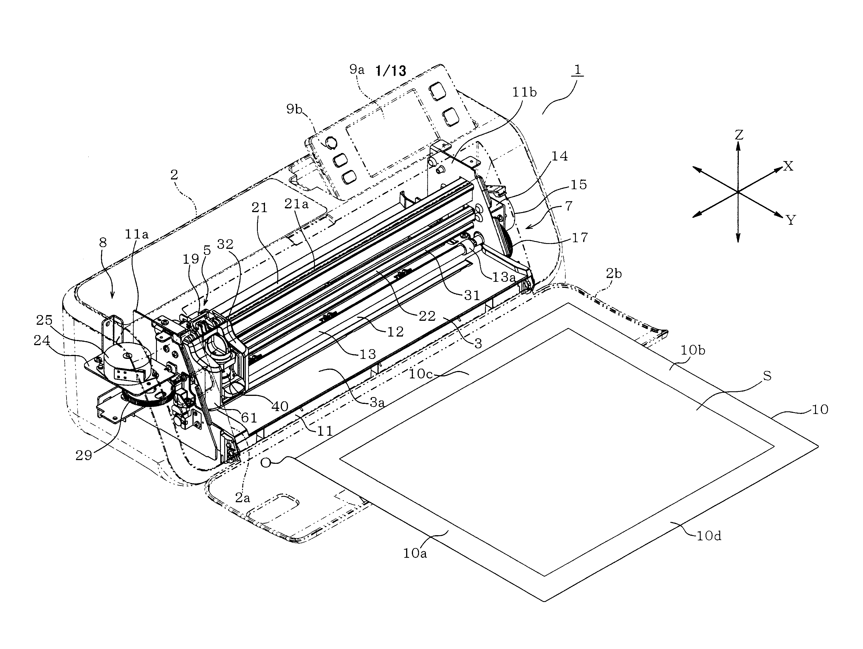
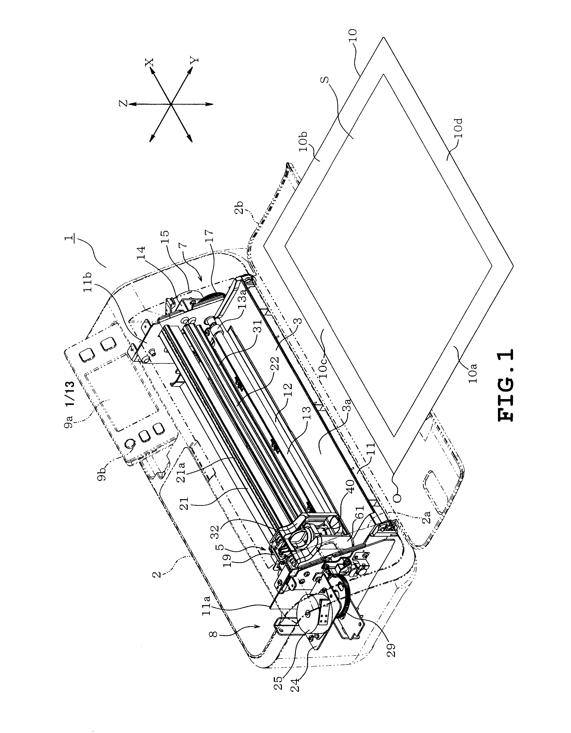
[0030]Several examples of the cutting apparatus will be described with reference to the accompanying drawings. Referring to FIG. 1, the cutting apparatus 1 of the first example includes a body cover 2 serving as a housing, a platen 3 provided in the body cover 2, a cutting head 5 serving as a cutting unit and a scanner 6 (see FIGS. 2 and 13) serving as an image reader.

[0031]The cutting apparatus 1 further includes a holding sheet 10 adapted to hold an object S which is to be cut and an image of which is to be read. The object S includes, for example, a plurality of types of objects to be cut such as paper sheet and cloth and paper carrying original drawing and photograph. Regarding the cutting apparatus 1 of the example, a plurality of types of cutter cartridges 40 is prepared according to the types of objects. One of the cutter cartridges 40 is to be attached to a cartridge holder 32 of a cutting head 5 as will be described later.

[0032]The body cover 2 is formed into the shape of a...


PUM


Abstract

A cutting apparatus includes a carriage with a cartridge holder to which a cutter cartridge is detachably attachable, a moving unit moving an object to be cut and the carriage relative to each other so that the object is cut by a cutter, and a pressing unit switchable between a fixing position where the pressing unit presses the cartridge attached to the cartridge holder to fix the cartridge and an open position where the pressing unit releases the cartridge from a fixed state. The cartridge has an abutment and the cartridge holder has an abutted portion against which the abutment abuts. At least one of the abutment and the abutted portion is tapered. The pressing unit presses the cartridge at the fixing position to fix the cartridge while the abutment is in abutment with the abutted portion, so that the cutter is held at a predetermined position.

Description

CROSS-REFERENCE TO RELATED APPLICATIONS[0001]This application is based upon and claims the benefit of priority from the prior Japanese Patent Application No. 2012-262584 filed on Nov. 30, 2012, the entire contents of which are incorporated herein by reference.BACKGROUND[0002]1. Technical Field[0003]The present disclosure relates to a cutting apparatus which cuts an object using a cutter cartridge.[0004]2. Related Art[0005]Cutting apparatuses have conventionally been known which cut an object to be cut, such as paper, according to cutting data thereby to obtain a predetermined pattern. The cutting apparatuses include a transfer mechanism transferring the object in a front-back direction (the Y direction) and a carriage moving a cutter cartridge having a cutter in a right-left direction (the X direction). A desired pattern is cut from the object by the aforementioned operations.[0006]The cutting apparatuses of the above-described type include a holder which is provided on the carriage...

Claims


Application Information

Patent Timeline
IPC IPC(8): B26F1/38
Inventor FUJIHARA, SHINYA
Owner BROTHER KOGYO KK
Why Eureka
Try Eureka