
Composite magnetic advertising mailing cards

Inactive Publication Date: 2008-08-21
SNAPNWIN
View PDF26 Cites 11 Cited by
  • Summary
  • Abstract
  • Description
  • Claims
  • Application Information

AI Technical Summary

Benefits of technology

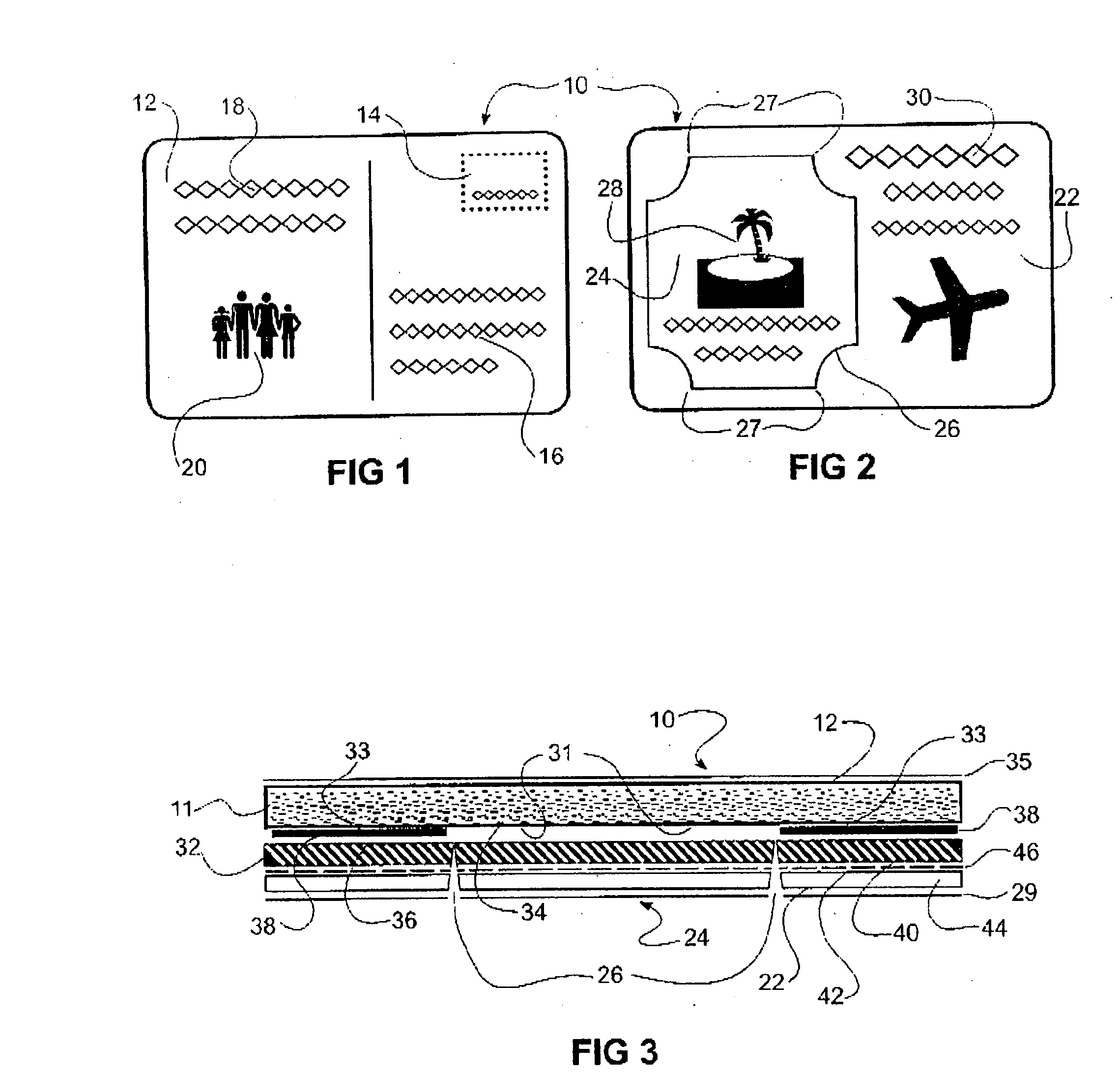
[0019]In its simplest form, the card contains a flat flexible magnet detachable from a paper cardstock. In some embodiments, preferably, the card is laminated with polymer on both sides, which protects the magnet, enhances the graphic image and enhances safe postal delivery.
[0020]Surprisingly, I have discovered that it is possible to not require an adhesive-frangible or otherwise between the removable magnetic portion and the remainder of the card. I have found that if the magnetic layer is die cut to the desired shape for the shaped detachable portion but leaving non-cut suitably located intermittent portions integral with the magnetic material to be retained to the card, that avoidance of use of an adhesive can be achieved. Non-use of an adhesive results in the card after the desired detachable portion has been detached in the newly visible region not being sticky by residual adhesive and, most preferably, having a clear surface viewable by a recipient to better see any data or design present thereon.
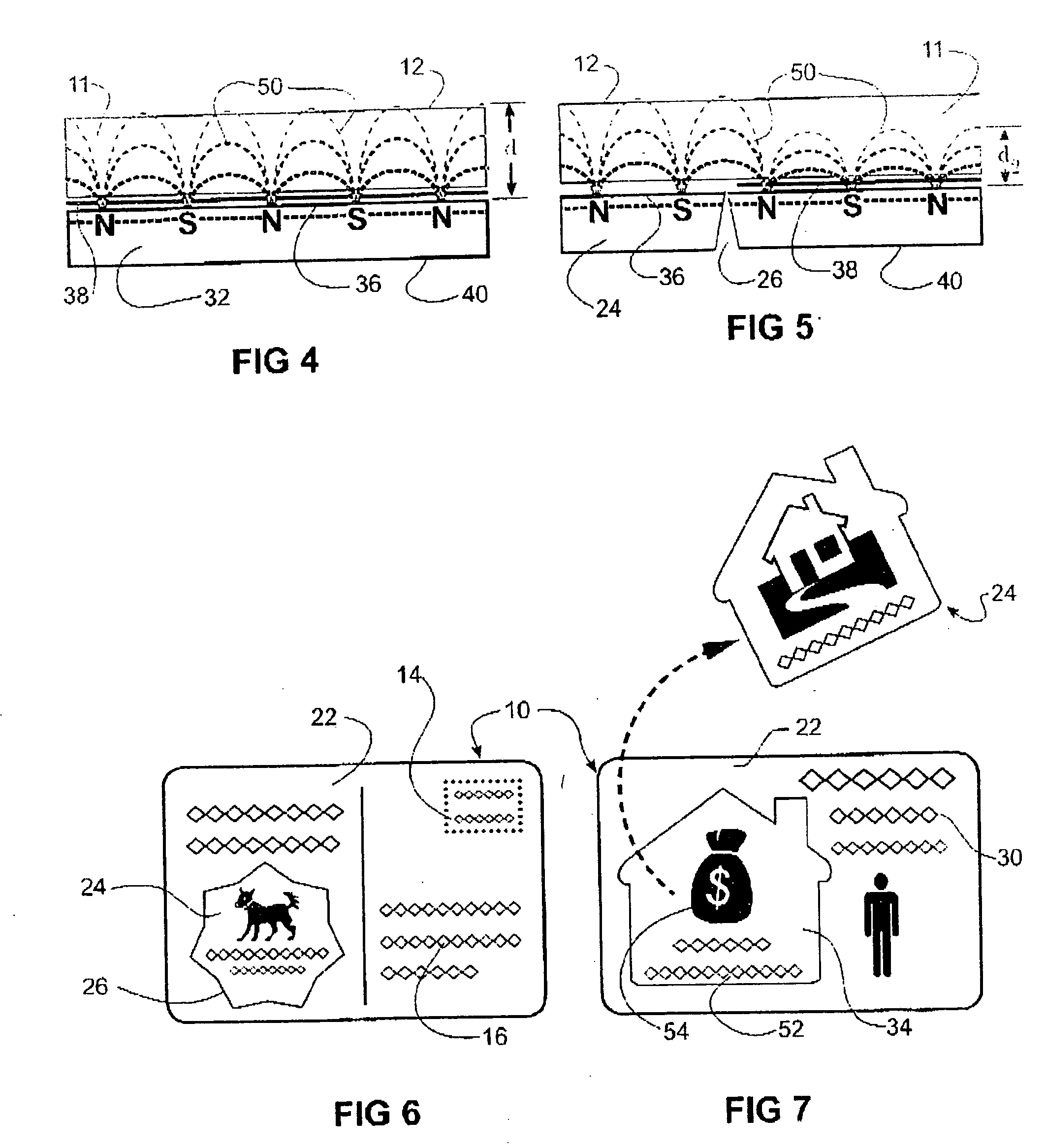
[0030]The magnetizing of the magnetic layer may be done at the time of its manufacture or in a preferred embodiment of this invention; it may be magnetized during the construction of the finished product. By magnetizing a part of the printing and die cutting process, the degree of magnetization may be chosen and a variation in that degree created to minimize the magnetic force of the completed card by having none or reduced magnetization in the non-removable area.
[0032]The card as described above is preferably cut from two similar sized printed master sheets (press sheets), which may contain space for many cards. This press sheet is preferably printed on a digital press thus allowing the front and back faces to be printed in alternate fashion, and also allowing the inclusion of variable data and ease of matching the front and back sides to be bonded together.

Problems solved by technology

With the above factors and the significant weight of the magnet, and the postal sorting problems of the inherent coercive force it has been difficult to achieve low cost mailings with magnets that were effective advertising mediums.
The limitation with the teaching of this example of prior art is that it leaves a magnet force facing outward, potentially jamming sortation equipment, the rough perforated edge to the magnet, the dual thickness affecting stacking of the finished product, and the loss of advertising space taken up by the face of the plain brown magnetic sheet.
This “ramp” is claimed to reduce mailing problems by making the stacking of the cards easier by reducing the sharp “bump” at the edge of the magnetic sheet adhered to the postcard which made the machine stacking of the postcard problematic.
The limitation of this prior art is the cost of assembling a complex multiple part piece and the mailing weight involved.
This has the continuing problem of not being automated mail compatible, and has the same issue as the aforesaid prior art with the unattractive brown magnetic face taking up a significant portion of one side of the card.
This prior art has the limitation of rendering the card non-planar like the two earlier instances noted above, and requiring an envelope for mailing.
This method limits the personalization possible, and requires multiple processes to manufacture cards and magnets separately and then bond the two together.
However this still entails the costly issue of being able to match separately produced magnets with a personalized ad or letter and the fact that the removable advertisement piece, the magnet, is hidden inside an envelope, reducing the odds of its use as a refrigerator magnet.

Method used


Image

  • Composite magnetic advertising mailing cards
  • Composite magnetic advertising mailing cards
  • Composite magnetic advertising mailing cards

Examples


Embodiment Construction

[0056]Thus, the invention provides a new and advantageous advertising card which is suitable for mass mailing to end-users. It is to be understood that the description terminology does not limit the uses of the invention.

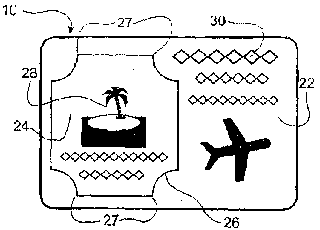
[0057]With reference to the drawings in more detail, FIGS. 1 and 2 illustrate the front and back sides, respectively, of a typical use of the invention as a postcard shown generally as 10. Card 10 may be of any shape but is rectangular in the embodiment shown, and has an address face 12 as shown in FIG. 1. Card 10 is partly composed of a planar cardstock 11 (FIG. 3) which may be of any printable material, such as coated or uncoated paper, plastic or a combination of suitable materials. On face 12 of this material 11, conventional postal indicia or stamp 14 and address 16 are placed as well as a variable or an unchanging static text message 18 and a variable image 20 or an unchanging status, if so desired.

[0058]The reverse side of card 10, as shown in FIG. 2, has a f...


PUM


Abstract

A composite magnetic card for bearing printed data and suitable for mailing purposes comprising(a) a first planar sheet of paper cardstock having a first face and second face;(b) a second planar sheet comprising a magnetic material having a first face and a second face and defining at least one detachable portion defined by a die cut while having suitably located portions integrally retained to non-detachable magnetic material of the second planar sheet;wherein the first sheet first face is sufficiently and suitably adhered with an adhesive to the second sheet first face to retain the detachable portion of the second sheet to the first sheet but wherein the adhesive is not disposed at first selected locations between the first sheet and the second sheet within the card. The resultant card after the detachable portion has been removed is adhesive-free to provide a non-sticky, clear area of the card, which may be readily used to clearly displace further desired data.

Description

FIELD OF THE INVENTION[0001]This invention relates to composite cards comprising a magnetic sheet and paper cardstock bearing advertising designations for direct and addressed postal service mailing and other means for distribution; more particularly to said cards having detachable portions; and to processes of manufacturing said cards.BACKGROUND OF THE INVENTION[0002]Flexible magnetic sheeting has been in use for a number of years to produce advertising specialty items commonly referred to as “refrigerator magnets”. These are used in both home and business environments and provide a long-lasting, effective, advertising medium when stuck to a metal surface, such as a refrigerator door, school locker, a filing cabinet and the like.[0003]Traditionally, the magnetic sheeting has been manufactured as a thin, calendared sheet of rubber or other polymers containing strontium ferrite powder. The magnetization has normally been accomplished at the time of manufacture and consists of imparti...

Claims


Application Information

Patent Timeline
IPC IPC(8): G09F1/00
CPCB42D15/006B42D15/025G09F7/04B42D2033/16G09F1/00B42D15/045B42D25/27B42D25/369B32B7/12B42D15/00G09F23/10
Inventor STAGG, MALCOLM J.
Owner SNAPNWIN
Learn More