
Multifunctional Floor Pods

a multi-functional, floor pod technology, applied in the direction of carpet cleaners, coupling device connections, refuse gathering, etc., can solve the problems of affecting the flow of vehicular traffic, affecting the cleaning of the top surface, and not providing a flush surface with the surrounding ground

Inactive Publication Date: 2008-08-21
OPTIMUS SERVICES
View PDF8 Cites 13 Cited by
  • Summary
  • Abstract
  • Description
  • Claims
  • Application Information

AI Technical Summary

Benefits of technology

[0022]A device which allows electrical power, fluids, gases, and links to data lines such as Ethernet, USB, and the like to a user in an indoor setting such as a residential home, an office building, a hospital operating room, a university laboratory, a retail store, a restaurant, or convention center is therefore described. The device also eliminates extraneous cables, wires, and hoses from the floor or elsewhere.
[0032]It is another object of this invention to provide a floor pod that can allow docking of devices adapted to meet the receptacles or connections presented on the pod.

Problems solved by technology

Located in areas where traffic control is a concern the latter type of bollard provides an obstruction to the flow of vehicular traffic.
However, previous out-door bollards, such as those described by Arlandis, have a top-surface which does not provide a flush surface with the surrounding ground when the bollard is in its retracted position.
This makes cleaning of the top-surface more difficult.
Further, the top “anchor” is unsightly.
Further, a top anchor or bulge from a dispensing bollard is a safety risk in that persons can easily trip over the bollard's bulge.
Further, multiple floor-pods in such environments could eliminate the amount of floor-space covered by wiring or other connections (a safety hazard because of the chance a person will trip over cabling or be exposed to a frayed cable).
However, standard dispensing bollards would not be adapted for use in such environments because of safety concerns.
While a flush surface would allow cleaning of the top portion of a bollard, accidental spillage of waste on or about standard bollards would result in contamination of the bollards in a manner that is not practical to clean and sterilize.

Method used


Image

  • Multifunctional Floor Pods
  • Multifunctional Floor Pods
  • Multifunctional Floor Pods

Examples


Embodiment Construction

[0045]As a general matter, a typical embodiment of the invention comprises a pod with various utility connections. The pod will usually have a first utility panel, which dispenses non-gas utilities such as electricity or data lines. The pod will then also have a second panel, usually opposite the first panel, which dispenses gas utilities, such as oxygen, and / or provides scavenging adaptors, such as vacuum. The second panel of gas / scavenging utilities typically presents a single, universal adaptor type. The selection of a universal adaptor provides ease of use and rapid interchange of connections. The universal adaptor may be a male style, such as an Ohmeda style hose barb or a Schrader (swivel or non-swivel) style hose barb; or the female connect versions of the same hose barbs. Also contemplated are alternative universal adaptor types such as Ohmeda or Schrader style NPT (National Pipe Thread) fittings (both male and female). Chemetron and Puritan style universal adaptors are also...


PUM


Abstract

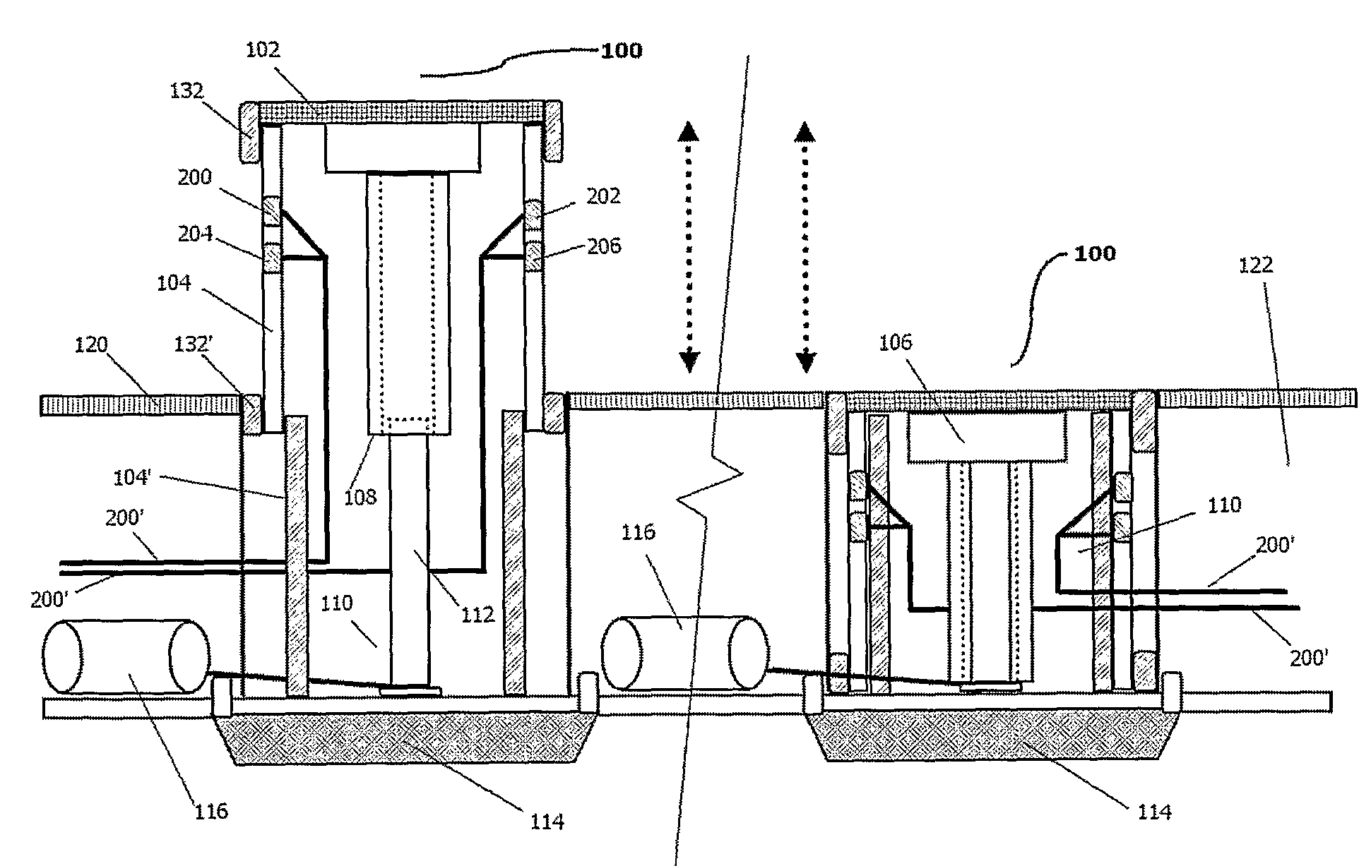
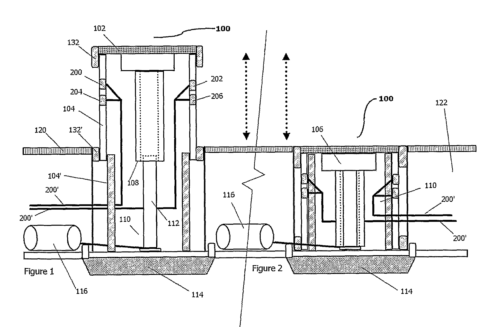
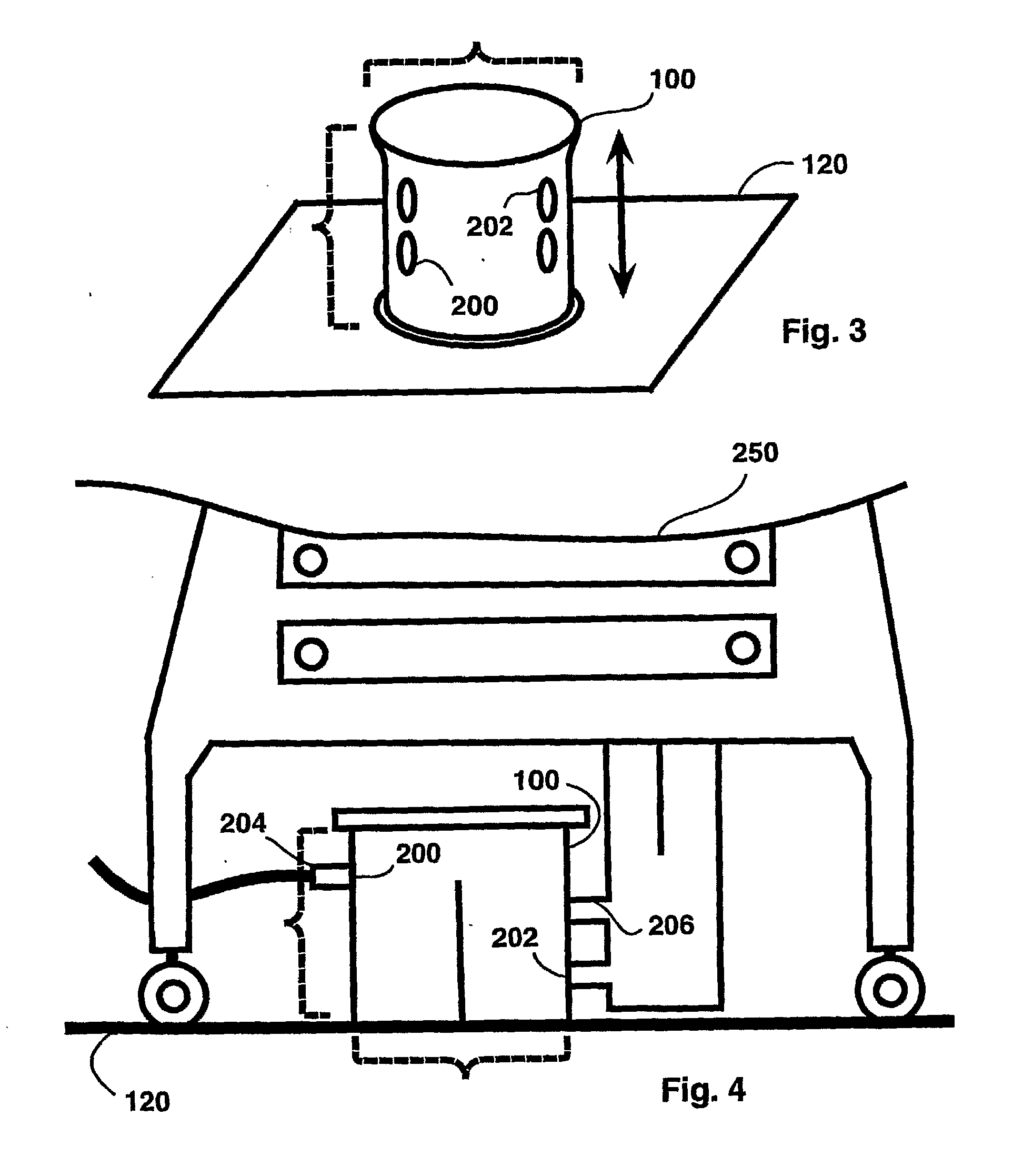
A floor pod (100) for indoor use, includes a vertically movable bollard adapted to present utilities and provide security function, presented in a watertight housing (110) is disclosed. The floor pod (100) provides a watertight seal (132) in both its distended and retracted state and also provides a flush, cleanable top surface with respect to the surrounding floor when retracted. The floor pod (10 may optionally be adapted with a universal adaptor for presenting gas and other like utilities All utilities are sourced from beneath th ground. The floor pod (100) is powered and may be controlled directly on the bollard or distant to the bollard by a wired or wireless connection thereto.

Description

CROSS-REFERENCE TO RELATED APPLICATIONS[0001]This application claims the benefit of provisional patent application U.S. Ser. No. 60 / 701,106, filed Jul. 20, 2005 by the present inventor. The contents of U.S. Ser No. 60 / 701,106 are expressly incorporated herein by reference thereto.[0002]The following references are hereby explicitly incorporated by reference thereto:[0003]U.S. Pat. No. 5,462,384[0004]U.S. Pat. No. 5,787,879[0005]U.S. Pat. No. 7,052,201[0006]Applications filed along with present application by current inventor on this date entitled:[0007]IN-CEILING FOCUS LOCATED SURGICAL LIGHTING[0008]HOSPITAL OPERATING ROOM RE-DESIGN[0009]AMBIENT LIGHTING IN HOSPITAL SURGICAL ENVIRONMENTS[0010]USE OF ULTRAVIOLET GERMICIDAL IRRADIATION IN HEALTH CARE ENVIRONMENTS[0011]IN-WALL WASTE RECEPTACLES FOR HOSPITAL AND LABORATORY ENVIRONMENTS[0012]RE-DESIGN OF OPERATING ROOM TABLES[0013]ROBOTIC FLOOR CLEANING WITH STERILE, DISPOSABLE CARTRIDGESFIELD OF THE INVENTION[0014]The present invention ...

Claims


Application Information

Patent Timeline
IPC IPC(8): E04C2/52
CPCA47L11/302A47L11/40A47L2201/00A61B19/0287A61B19/0288A61B2019/0202H01R27/02A61B2019/0267B01L1/50B65F1/0093B65F1/06E04B5/48H01R13/005A61B2019/025A61B2050/314A61B2050/005A61B50/13A61B50/36A61B50/362
Inventor MANGIARDI, JOHN R.
Owner OPTIMUS SERVICES
Learn More