Locking Pliers

a technology of locking pliers and pliers, which is applied in the field of pair of locking pliers, can solve the problems of increasing cost and inconvenient assembly work, and achieve the effect of saving space and cost and making assembly work more convenien

Active Publication Date: 2008-08-21
WU NA
View PDF3 Cites 16 Cited by
  • Summary
  • Abstract
  • Description
  • Claims
  • Application Information

AI Technical Summary

Benefits of technology

[0015]By such arrangements, the restricting member not only saves space and cost for it needs no additional subassemblies, but also makes the assembling work more convenient.

Problems solved by technology

In addition, the restricting portion P53 of the restricting member P5 should cooperate with a stopping subassembly P34 and that increases the cost and makes the assembling work more inconvenient.

Method used


Image

  • Locking Pliers
  • Locking Pliers
  • Locking Pliers

Examples


Embodiment Construction

[0023]The present invention will be more clear from the following description when viewed together with the accompanying drawings, which show, for purpose of illustrations only, the preferred embodiment in accordance with the present invention.

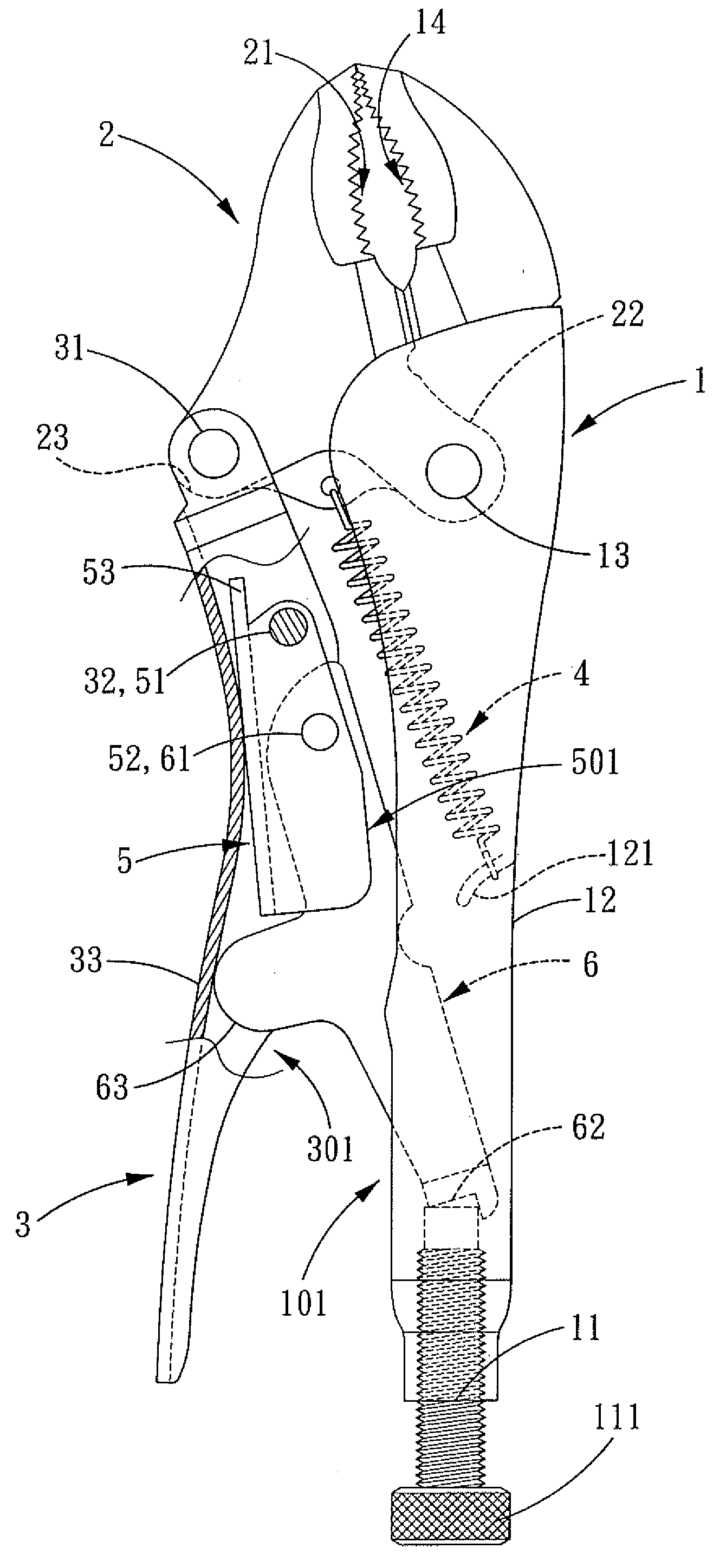
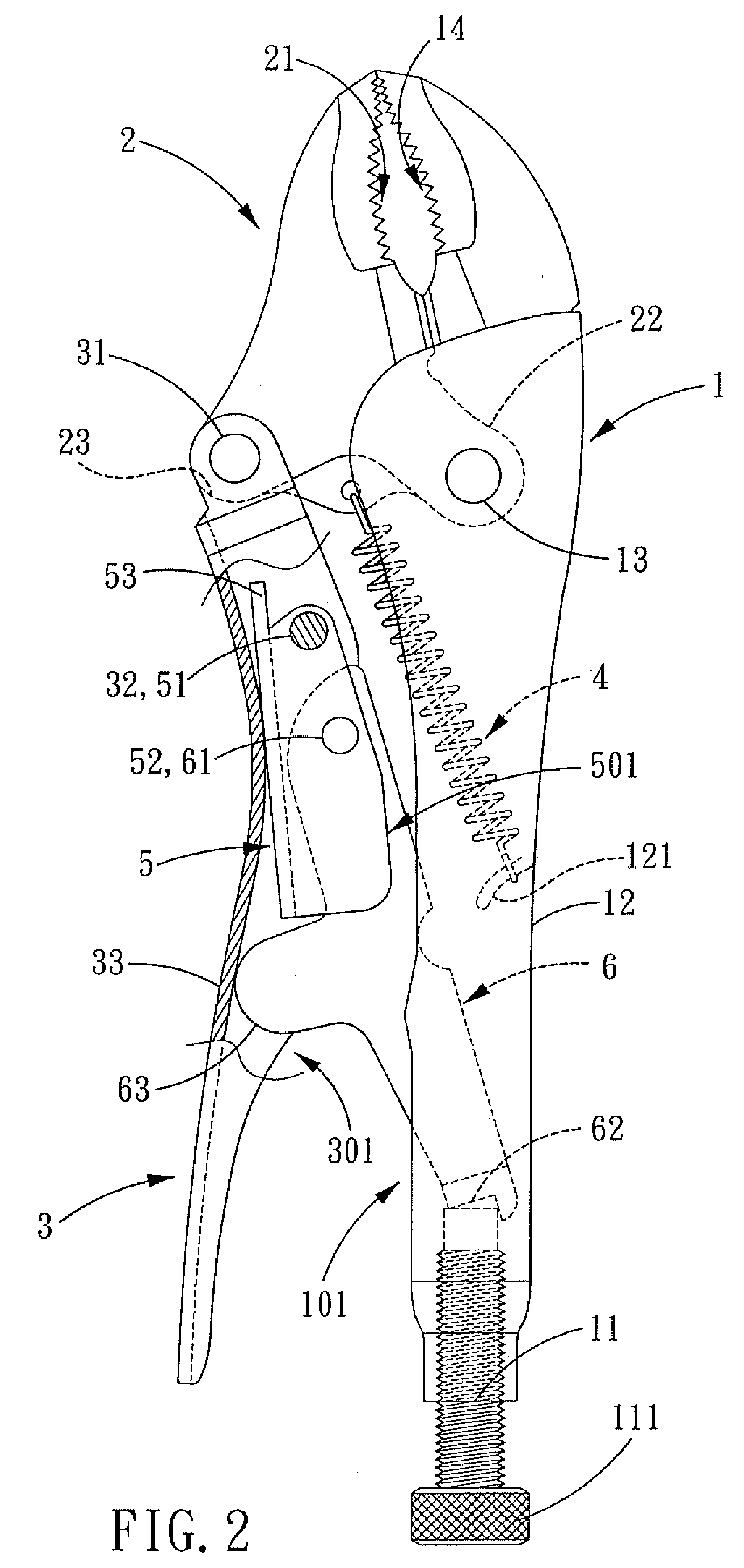
[0024]Referring to FIGS. 2-7, a pair of locking pliers in accordance with the present invention comprises a fixed handle 1, an adjustable jaw 2, a side handle 3, an elastic member 4, a restricting member 5 and a linking member 6.

[0025]The fixed handle 1 is provided with a U-shaped groove 101. A receiving portion 11 is defined at one end of the fixed handle 1. A supporting member 111 that is aligned with the groove 101 is screwed in the receiving portion 11. One end of the receiving portion 11 is connected with a holding portion 12, and a hook-shaped rib 121 is formed in the middle section of the bottom of the groove 101. One end of the holding portion 12 connects a pivoting portion 13, and one end of the pivoting portion 13 is connected with a...


PUM


Abstract

A restricting member with an engaging structure for a pair of locking pliers comprises a first pivoting portion, a second pivoting portion and the engaging structure. The engaging structure extends out of an upper part of the restricting member, so that it can be positioned in a groove of a side handle, and makes a supporting portion of a linking member press against the groove of the side handle. The restricting member not only saves space and cost for it needs no additional subassemblies, but also makes the assembling work more convenient.

Description

BACKGROUND OF THE INVENTION[0001]1. Field of the Invention[0002]The present invention relates to a pair of locking pliers, and more particularly to an engaging structure for a pair of locking pliers.[0003]2. Description of the Prior Art[0004]A pair of locking pliers of an U.S. Pat. No. 6,626,070, as shown in FIG. 1, comprises a fixed handle P1, an adjustable jaw P2, a side handle P3, an elastic member P4, a restricting member P5 and a linking member P6.[0005]The fixed handle P1 is provided with a U-shaped groove P101. One end of the fixed handle P1 is defined with a receiving portion P11 in which is screwed a supporting member P111 that is aligned with the groove P101, and one end of the receiving portion P11 is connected to a gripping portion P12. A hook-shaped rib is formed in the middle section of the bottom of the groove P101, which is aligned with the gripping portion P12. One end of the gripping portion is connected to a pivoting portion P13, and one end of the pivoting portio...

Claims


Application Information

Patent Timeline
Patent Type & Authority Applications(United States)
IPC IPC(8): B25B7/14
CPCB25B7/123
Inventor WU, MING-CHIEH
Owner WU NA
Why Eureka
Try Eureka