
Image Processing Device

a processing device and image technology, applied in the field of image processing devices, can solve the problems of inability to accurately identify from the top view image the solid object present near the vehicle, the inability to accurately display the entire image of the solid object in the top view image, and the difficulty of using the top view image for parking assistance, etc., to achieve accurate information for users and high safety driving assistance

Inactive Publication Date: 2008-08-21
ALPINE ELECTRONICS INC
View PDF16 Cites 48 Cited by
  • Summary
  • Abstract
  • Description
  • Claims
  • Application Information

AI Technical Summary

Benefits of technology

[0010]The present invention has been made in view of the above circumstances, and it is an object of the present invention to provide an image processing device capable of enabling accurate recognition of a solid object present near a vehicle and displaying the solid object.
[0011]Further, the present invention provides a navigation system capable of assisting driving by displaying data of captured images.
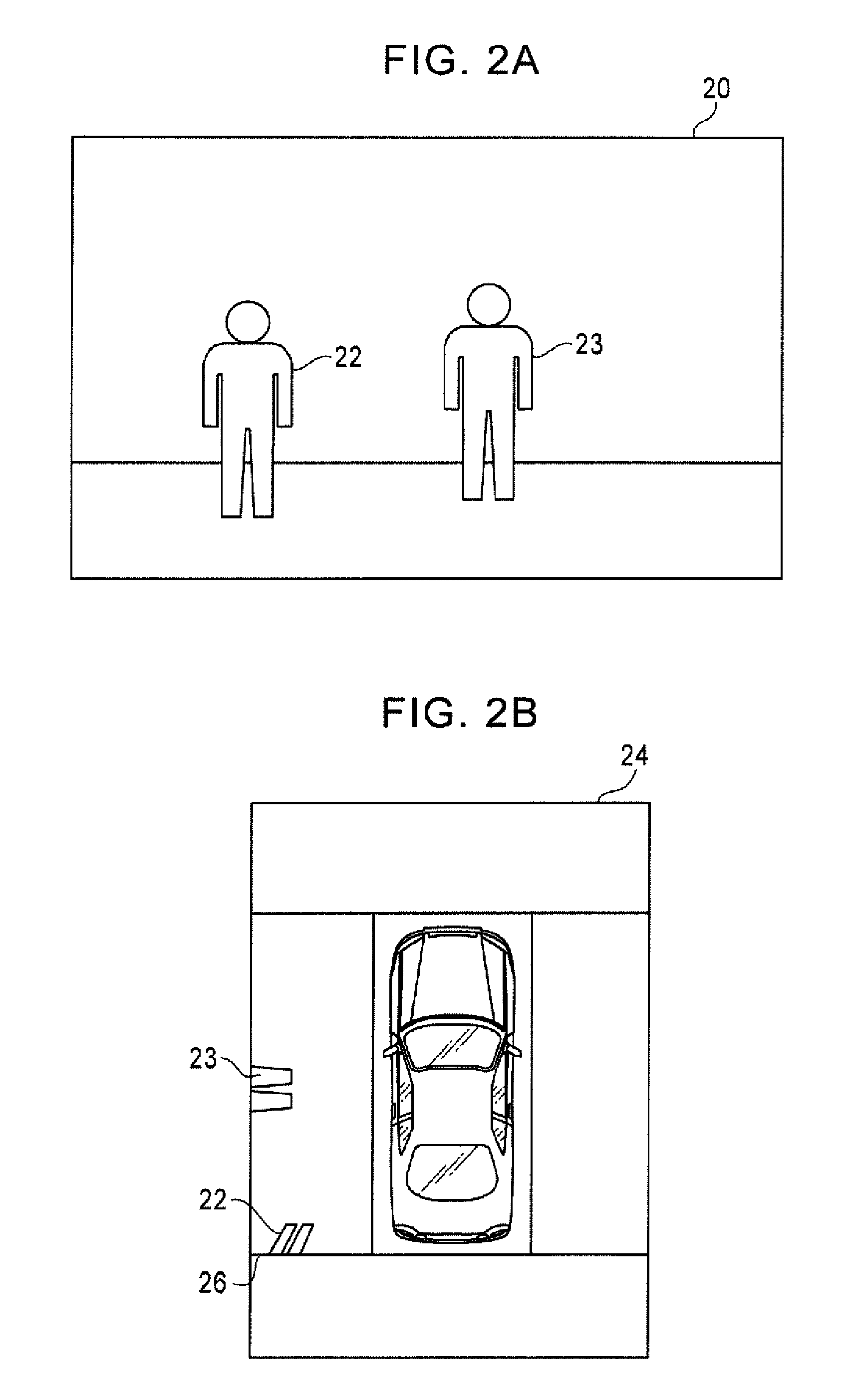
[0016]According to one aspect, even if the solid object can disappear or be deformed due to the influence of the joined portions of the viewpoint-converted image or due to the limitation of the display range of the viewpoint-converted image, the solid object image is generated in accordance with the solid object extracted from the data of the captured images, and the generated solid object image is synthesized with the viewpoint-converted image. Accordingly, it is possible to accurately inform a user of the presence of the solid object present near the vehicle, and thus to provide highly safe driving assistance with the use of the data of the captured images.

Problems solved by technology

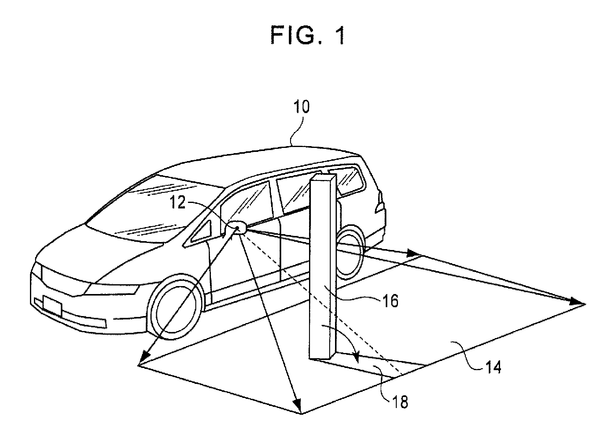
Further, because the top view image is generated on the basis of the ground of the surroundings of the vehicle, the top view image cannot always accurately display the entire image of the solid object 16.
As a result, a user cannot accurately identify from the top view image the solid object present near the vehicle.
Thus, it is difficult to use the top view image for parking assistance and so forth.

Method used


Image

  • Image Processing Device
  • Image Processing Device
  • Image Processing Device

Examples


Embodiment Construction

[0028]Preferred embodiments of the present invention will be described in detail below with reference to the drawings.

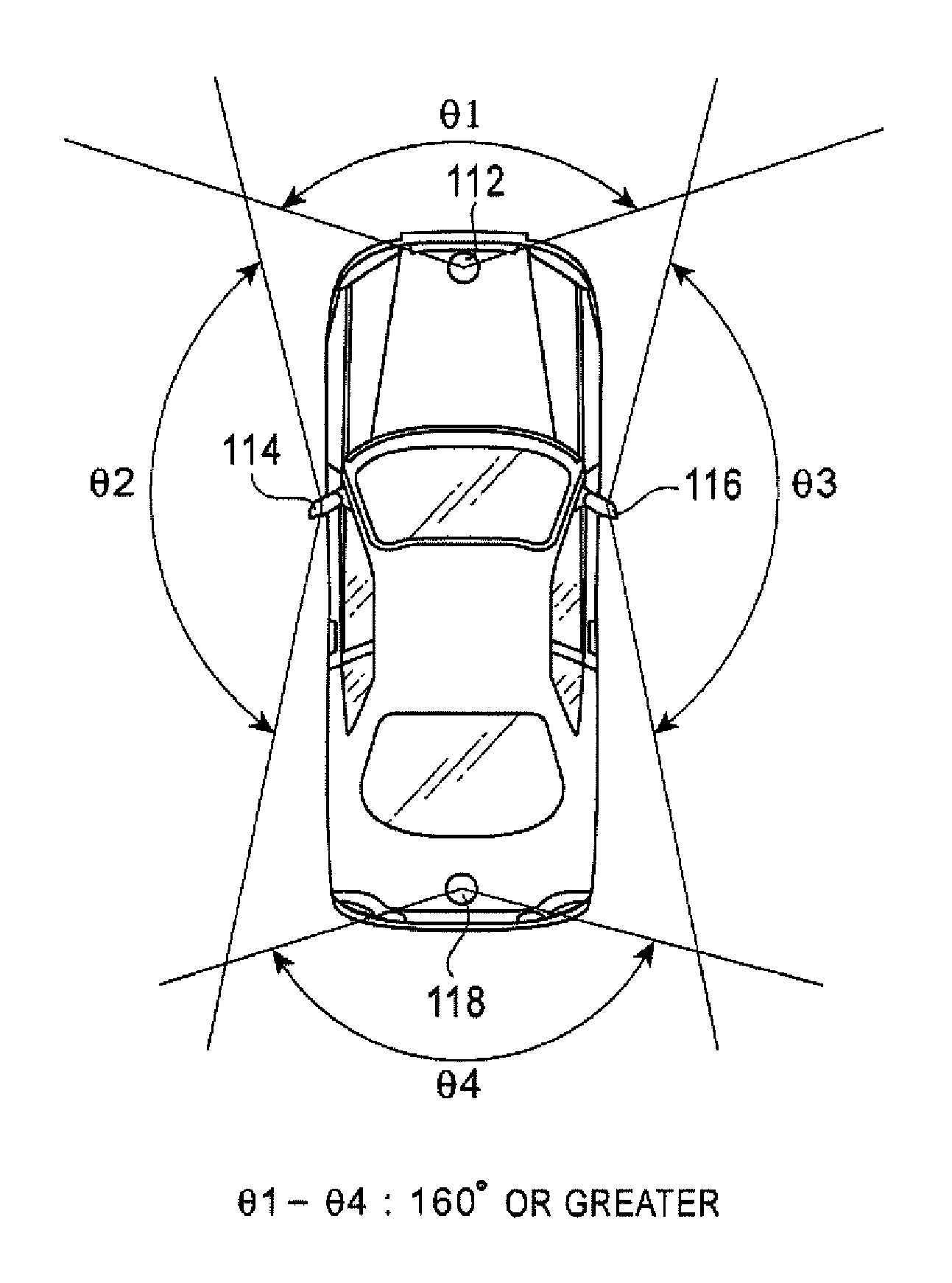
[0029]FIG. 3A is a block diagram illustrating a configuration of an image processing device 100 according to an embodiment of the present invention. The image processing device 100 is configured to include an input unit 102 to which a user inputs an instruction, a vehicle state sensor 104 for outputting a state of a vehicle, such as the speed and the gear shift position of the vehicle, a control unit 106 for controlling respective units in accordance with an image processing program, a display control unit 108 for displaying a top view image on a display 110, and image capturing cameras 112 to 118 for capturing images of the surroundings of the vehicle.

[0030]FIG. 3B is a block diagram illustrating a functional configuration of the control unit 106. The control unit 106 includes a viewpoint conversion unit 120, a solid object extraction unit 122, a solid object image ...


PUM


Abstract

The present invention provides an image processing device capable of enabling accurate recognition of a solid object present near a vehicle and displaying the solid object. The image processing device includes a viewpoint conversion unit for receiving data of images captured by at least one image capturing camera and generating a top view image, a solid object extraction unit for detecting a solid object from the data of the images captured by the at least one image capturing camera and extracting the solid object, a solid object image generation unit for generating a solid object image in accordance with the solid object extracted by the solid object extraction unit, and an image synthesis unit for synthesizing the solid object image generated by the solid object image generation unit with the top view image generated by the viewpoint conversion unit.

Description

RELATED APPLICATIONS[0001]The present application claims priority to Japanese Patent Application Number 2007-040765, filed Feb. 21, 2007, the entirety of which is hereby incorporated by reference.BACKGROUND OF THE INVENTION[0002]1. Field of the Invention[0003]The present invention relates to an image processing device for displaying an image of the surroundings of a vehicle captured by at least one image capturing camera mounted on the vehicle, and particularly to a technique of converting captured images into an image looking down from a point of view above the vehicle and displaying the converted image.[0004]2. Description of the Related Art[0005]Along with an increase in the use of image capturing cameras mounted on automobiles, applications using captured image data have been increasing. Many of such applications are for assisting a driver in driving and for improving the safety of a vehicle in driving and parking of the vehicle. For example, in a system which captures an image ...

Claims


Application Information

Patent Timeline
Patent Type & Authority Applications(United States)
IPC IPC(8): H04N7/18
CPCG06K9/00805G06V20/58
Inventor IMAMURA, KOSUKE
Owner ALPINE ELECTRONICS INC
Learn More