Image sensor device

a sensor device and image technology, applied in the field of image sensor devices, can solve the problems of deteriorating movement precision of an object to be moved, affecting the realization of a smaller, lighter image capturing device, etc., and achieve the effect of resistance to movement of a movable unit, and high precision of movement of an obj

Inactive Publication Date: 2008-08-21
KONICA MINOLTA OPTO
View PDF5 Cites 97 Cited by
  • Summary
  • Abstract
  • Description
  • Claims
  • Application Information

AI Technical Summary

Benefits of technology

[0011]By providing a wire for the beam unit for supporting the movable unit without providing a special structure of installing a wire for electrically connecting the image sensor and an external circuit, when the movable unit moves relative to the fixed unit, resistance to movement of the movable unit from a structure other than the beam unit is suppressed. Thus, the small-sized sensor device with high precision of movement of an object to be moved can be provided.
[0014]Therefore, an object of the present invention is to provide a small-size image sensor device with high precision of movement of an object to be moved.

Problems solved by technology

It hinders realization of a smaller, lighter image capturing device.
Consequently, at the time of driving the movable substrate, a reaction force according to a force required to deform the flexible substrate acts on the movable substrate, and it becomes a factor of disturbing fine driving of the movable substrate.
That is, movement precision of an object to be moved deteriorates.

Method used


Image

  • Image sensor device
  • Image sensor device
  • Image sensor device

Examples


Embodiment Construction

[0024]Embodiments of the present invention will be described hereinbelow with reference to the drawings.

Image Capturing Apparatus

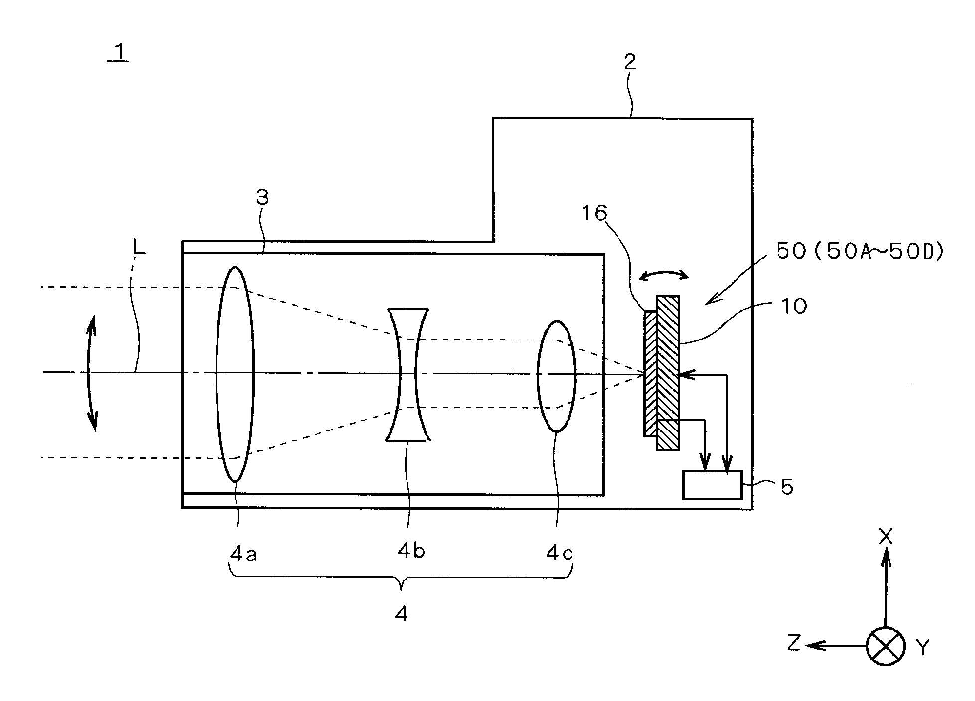
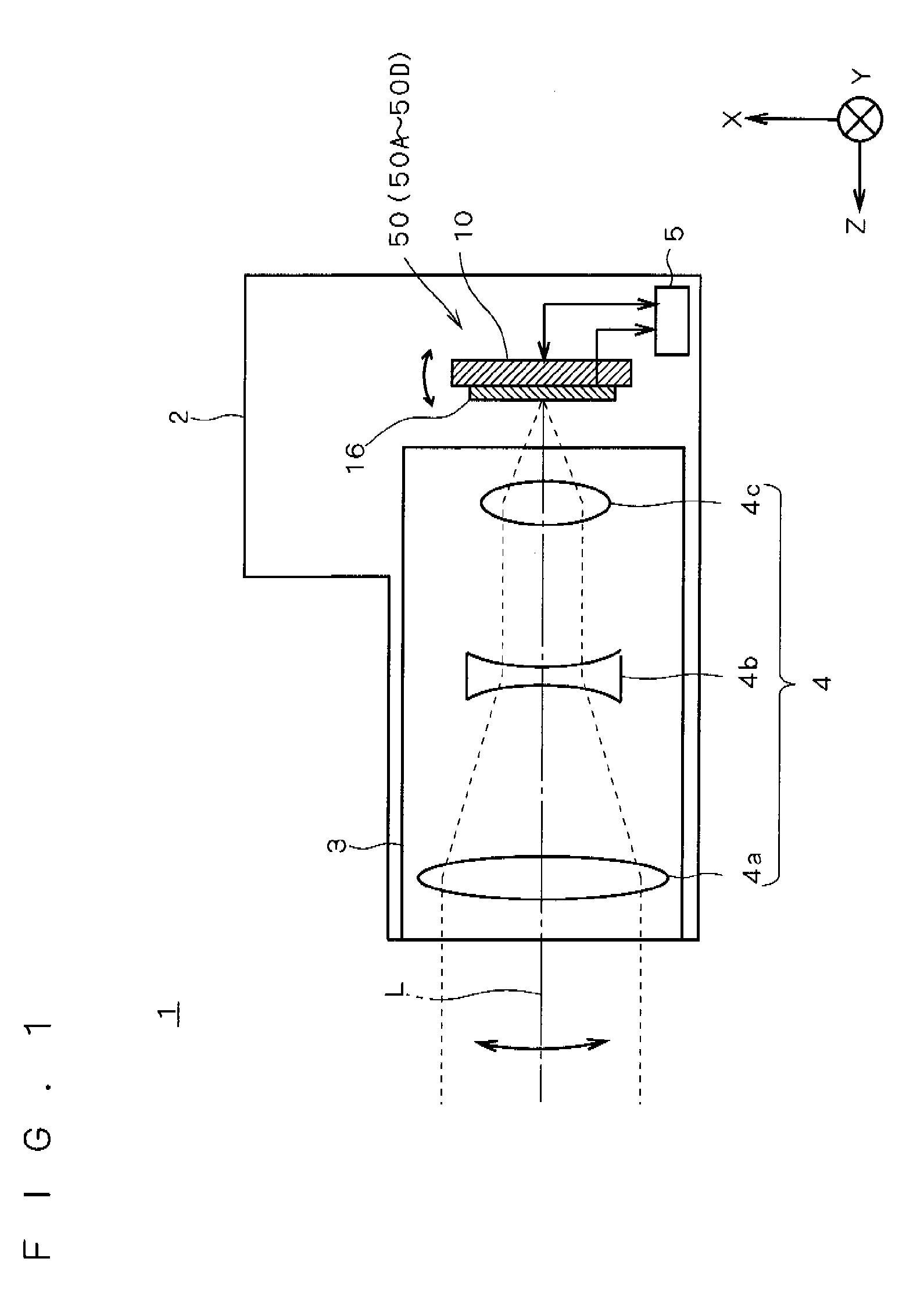
[0025]FIG. 1 is a cross section view schematically showing the configuration of an image capturing apparatus 1 as an embodiment of the present invention. In FIG. 1 and subsequent drawings, three axes of X, Y, and Z orthogonal to each other are shown to clarify the azimuth relations.

[0026]The image capturing apparatus 1 is a digital camera having a so-called camera shake correcting function and including, mainly, a body (camera body) 2 of the image capturing apparatus and a camera cone 3 as an optical system including a lens group 4.

[0027]The lens group 4 has a plurality of lenses 4a, 4b, and 4c and can adjust the magnification and a focal point by properly changing the distance between the lenses.

[0028]The camera body 2 has a sensor device 50 having a driving mechanism 10 and an image pickup device 16, and a controller 5 which controls the entire image cap...


PUM


Abstract

An object of the present invention is to provide a small-sized image sensor device having high precision of moving an object to be moved. The image sensor device includes: a fixed unit; a movable unit including an image sensor; a beam unit fixed to the fixed unit and movably supporting the movable unit; a driving unit for applying a driving force for moving the movable unit; and a wire unit provided for the beam unit and electrically connecting the image sensor and an external circuit.

Description

[0001]This application is based on application No. 2007-037615 filed in Japan, the contents of which are hereby incorporated by reference.BACKGROUND OF THE INVENTION[0002]1. Field of the Invention[0003]The present invention relates to an image sensor device.[0004]2. Description of the Background Art[0005]In recent years, a camera having a function of correcting image blurring which occurs in a captured image due to a shake of a hand holding the camera or the like (so-called camera-shake correcting function) is being widely spread. Particularly, in a light-weight image capturing device such as a small-sized digital camera or a cellular phone with an image capturing function, a handshake occurs easily. It is therefore demanded to provide the device with the handshake correcting function.[0006]To realize the camera shake correcting function, however, a driving mechanism for driving various members such as an image pickup device is necessary. It hinders realization of a smaller, lighter...

Claims


Application Information

Patent Timeline
Patent Type & Authority Applications(United States)
IPC IPC(8): H04N5/335G03B5/00G03B17/00H04N5/232
CPCH04N5/2253H04N5/23248G03B2205/0038G03B17/17G03B2205/0053G03B5/00H04N23/54H04N23/68
Inventor TANIMURA, YASUTAKAKOSAKA, AKIRAYAMAMOTO, NATSUKIHAMADA, MASATAKAHARA, YOSHIHIRO
Owner KONICA MINOLTA OPTO
Why Eureka
Try Eureka