Magnetoresistive device, magnetic head, magnetic storage apparatus, and magnetic memory

a technology of magnetoresistance and magnetic head, which is applied in the field of magnetoresistance devices, magnetic head, magnetic storage apparatus, and magnetic memory, can solve the problems of insufficient sensitivity to the change in magnetoresistance and degraded device performan

Inactive Publication Date: 2008-08-21
FUJITSU LTD
View PDF0 Cites 28 Cited by
  • Summary
  • Abstract
  • Description
  • Claims
  • Application Information

AI Technical Summary

Problems solved by technology

Since with a CIP structure the sense current is large, the device performance may be degraded due to migration in materials used in the spin-valve film structure.
However, even if the above-described materials are applied to the magnetization free layer or the magnetization pinned layer, the sensitivity to the change in magnetoresistance will be insufficient if the read gap is further narrowed along with the improvement of the recording density in the future.

Method used


Image

  • Magnetoresistive device, magnetic head, magnetic storage apparatus, and magnetic memory
  • Magnetoresistive device, magnetic head, magnetic storage apparatus, and magnetic memory
  • Magnetoresistive device, magnetic head, magnetic storage apparatus, and magnetic memory

Examples


first embodiment

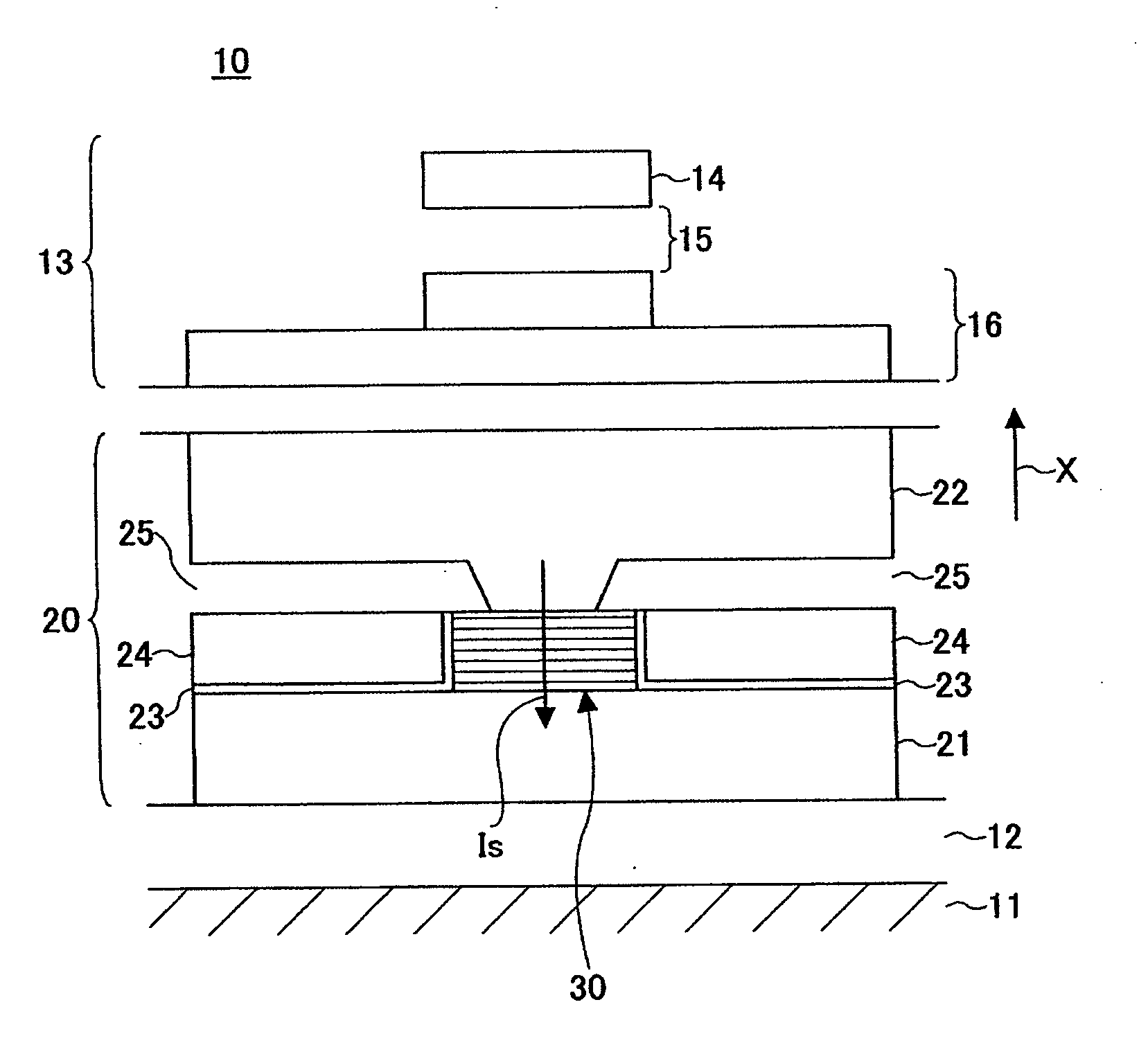
[0032]FIG. 1 is a schematic diagram illustrating the cross-sectional structure of a hybrid magnetic head 10 according to the first embodiment of the invention. The magnetic head 10 has a magnetoresistive device 20 and an induction type writing device 13. The arrow X represents a direction of movement of a magnetic recording medium (not shown) that faces the magnetoresistive device. The magnetoresistive device 20 is formed on a flat ceramic (e.g., Al2O3—TiC) substrate 11 that serves as the base of a head slider (not shown). On the magnetoresistive device 20 is formed the induction type writing device 13.

[0033]The induction type writing device 13 includes a top magnetic pole 14 having a width corresponding to the track width of the facing magnetic recording medium, a bottom magnetic pole 16 extending parallel to the top magnetic pole 14, and a writing gap layer 15 formed of a non-magnetic material and inserted between the top and bottom magnetic poles 14 and 16. The induction type wri...

second embodiment

[0097]FIG. 10 is a schematic cross-sectional diagram of a magnetoresistive effect film applied to a magnetic head according to the second embodiment of the invention. In the second embodiment, a tunnel magnetoresistive film (hereinafter, referred to as a TMR film) is applied in place of the GMR film of the first embodiment to the magnetoresistive device, and other structures and arrangements are the same as those in the first embodiment. Accordingly, explanation for the magnetic head is omitted here.

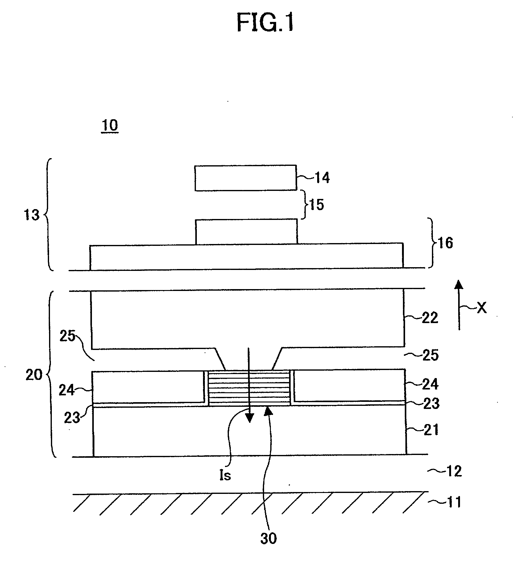
[0098]FIGS. 10-15 illustrate structural examples 1-6 of the TMR film used in the magnetoresistive device 20 of the second embodiment. The TMR films 70, 71, 72, 73, 74A and 74B of the structural examples 1-6 of the second embodiment have the same structures as the GMR films 30, 40, 50, 60, 65A and 65B shown in FIGS. 2-7, except for the non-magnetic insulating layers 37a and 47a which are replacements for the non-magnetic metal layers 37 and 47, respectively, of the first embodiment.

[0099]...

third embodiment

[0104]FIG. 16 is a plan view of a magnetic storage apparatus according to the third embodiment of the present invention. The magnetic storage apparatus 90 has a housing 91 which accommodates a hub 92 driven by a spindle (not shown), a magnetic recording medium 93 fixed to the hub 92 and rotated by the spindle, an actuator unit 94, a suspension supported by the actuator unit 94 and driven in a radial direction of the magnetic recording medium 93, and a magnetic head 98 supported by the suspension 96.

[0105]The magnetic recording medium 93 can be of an in-plane magnetic recording type or a perpendicular magnetic recording type, and may be a recording medium having oblique anisotropy. The magnetic recording medium 93 is not limited to a magnetic disk, and can be a magnetic tape.

[0106]The magnetic head 98 includes the magnetoresistive device 20 and the induction type writing device 13 formed over the ceramic substrate 11, as illustrated in FIG. 1. The induction type writing device 13 may...


PUM

PropertyMeasurementUnit
thicknessaaaaaaaaaa
thicknessaaaaaaaaaa
thicknessaaaaaaaaaa

Abstract

A CPP-type magnetoresistive device includes a magnetization pinned layer, a magnetization free layer, and a non-magnetic layer provided between the magnetization pinned layer and the magnetization free layer. At least one of the magnetization free layer and the magnetization pinned layer is formed of CoFeGe, and the CoFeGe has a composition falling within a range defined by line segments connecting coordinate points A, B, C, and D in a ternary composition diagram where the point A is (42.5, 30, 27.5), the point B is (35, 52.5, 12.5), the point C is (57.5, 30.0, 12.5), and the point D is (45.0, 27.5, 27.5), and where each of the coordinate points is represented by content percentage of (Co, Fe, Ge) expressed by atomic percent (at. %).

Description

BACKGROUND OF THE INVENTION[0001]1. Field of the Invention[0002]The present invention relates to a magnetoresistive device used to reproduce information from a magnetic recording medium or storage devices, and more particularly, to a current-perpendicular-to-plane (CPP) magnetoresistive device in which a sense current flows in a direction of perpendicularly through multiplayer planes.[0003]2. Description of the Related Art[0004]In recent years and continuing, giant magnetoresistive (GMR) devices are used as information reproducing devices of the magnetic heads in magnetic storage apparatuses to reproduce information from magnetic recording media. The GMR device makes use of the giant magnetoresistive effect, which means change in resistance induced by an external magnetic field. With the GMR device, changes in direction of the magnetic field leaking from the magnetic recording medium are detected and converted into changes in electric resistance when reproducing information from the...

Claims


Application Information

Patent Timeline
Patent Type & Authority Applications(United States)
IPC IPC(8): G11B5/33
CPCB82Y10/00G11B2005/3996G11B5/3929B82Y25/00G06K19/07732G06F2213/0042
Inventor JOGO, ARATASHIMIZU, YUTAKA
Owner FUJITSU LTD
Why Eureka
Try Eureka