Storage Device for Use in Fiber Optic Communication Systems and Method of Using the Same

a technology of fiber optic communication system and storage device, which is applied in the direction of flexible lead accommodation, optical light guide, instruments, etc., can solve the problems of laborious storage procedure, excessive complexity of fiber management, and difficulty in storing excess fiber for operators

Inactive Publication Date: 2008-08-21
AFL COMM LLC
View PDF10 Cites 32 Cited by
  • Summary
  • Abstract
  • Description
  • Claims
  • Application Information

AI Technical Summary

Problems solved by technology

As the number of fibers deployed in fiber optic communication systems has increased, the management of fibers has become exceedingly complex.
As the number of fibers increases, this excess length multiplies, causing problems in management of the excess lengths of fibers and cables in splice enclosures, fiber distribution frames, cross-connects, multi-fiber installations, FTTX drops, and optical devices and photonic assemblies.
However, even for lower fiber count cable splicing, the storage of the excess fiber can present significant difficulties for the operator and for the design of a splice enclosure which holds the splices.
This storage procedure is tedious and requires a great amount of effort and skill by the operator.
More importantly, however, if the radius of a loop or coil of fiber is less than the bending radius of the fiber, excess bending losses will occur during the transmission of information through the fibers.
Moreover, existing storage procedures have a risk of breaking or damaging the fibers, a risk which only increases as the number of fibers to be stored increases.
After the excess fiber is stored, a different problem occurs in that the operator must often return to the splice storage enclosure in order to re-route fibers, to splice additional fibers, to repair or replace existing fibers, to add additional branch cables or to splice previously un-terminated fibers.
In each of these cases, re-entry is complicated and time consuming.
Thus, even if the initial storage of excess fiber within the storage enclosure is done properly, the situation within the enclosure tends to degrade with each re-entry to the splice enclosure.
Management of excess cable of jumper cables used in fiber distribution frames and cross-connect cabinets presents similar problems.
The excess jumper length becomes unmanageable, especially as the number of jumper cables increases.
These jumper cables frequently hang down and tangle together, and thus present problems of proper identification, management, and reconfiguration for the operator, problems which are similar to those present in the storage enclosure described above.
A multi-fiber cable installation also presents similar problems with provisioning slack loops of cable.
However, this method suffers from the problem that the resulting coil is user dependent, and often introduces a twist into the cable.
Moreover, the coil must be hung and re-hung, which is time consuming, and in the case of underground cables or cable storage in a vault, space imitations make storage of such loops difficult.
While the snow shoe method provides a much neater and ascetically pleasing slack installation, it has limited slack length capacity.
Management of excess lengths of FTTX drop cables produces similar difficulties for the operator.
However, these pre-terminated cables require the use of set cable lengths that have excess length.
Moreover, many drop cables have a non-circular (e.g., flat or nearly rectangular) cross section, which magnifies the problems with coiling excess cable length by hand.
In addition, a coil of such a non-circular, flat cable may be subject to severe wind loading, placing excess stress on the attachment of the coil wherever it is located.
Many similar problems arise in the management of excess fiber length within optical assemblies and fiber optic test equipment.
Such subassemblies present problems similar to those described above.
An additional problem with this type of manufacturing method is that a precise length of fiber is required on each side of the splice point in order to ensure that the operator can wind a specific number of wraps around the slack fiber “racetrack”.

Method used


Image

  • Storage Device for Use in Fiber Optic Communication Systems and Method of Using the Same
  • Storage Device for Use in Fiber Optic Communication Systems and Method of Using the Same
  • Storage Device for Use in Fiber Optic Communication Systems and Method of Using the Same

Examples


Embodiment Construction

[0039]Hereinafter, exemplary embodiments of the present invention will be described in detail with reference to the accompanying drawings. However, the present invention is not limited to the exemplary embodiments disclosed hereinafter, but can be implemented in diverse forms. The matters defined in the description, such as the detailed construction and elements, are nothing but specific details provided to assist those of ordinary skill in the art in a comprehensive understanding of the invention, and the present invention is only defined within the scope of the appended claims. In the whole description of the present invention, the same drawing reference numerals are used for the same elements across various figures.

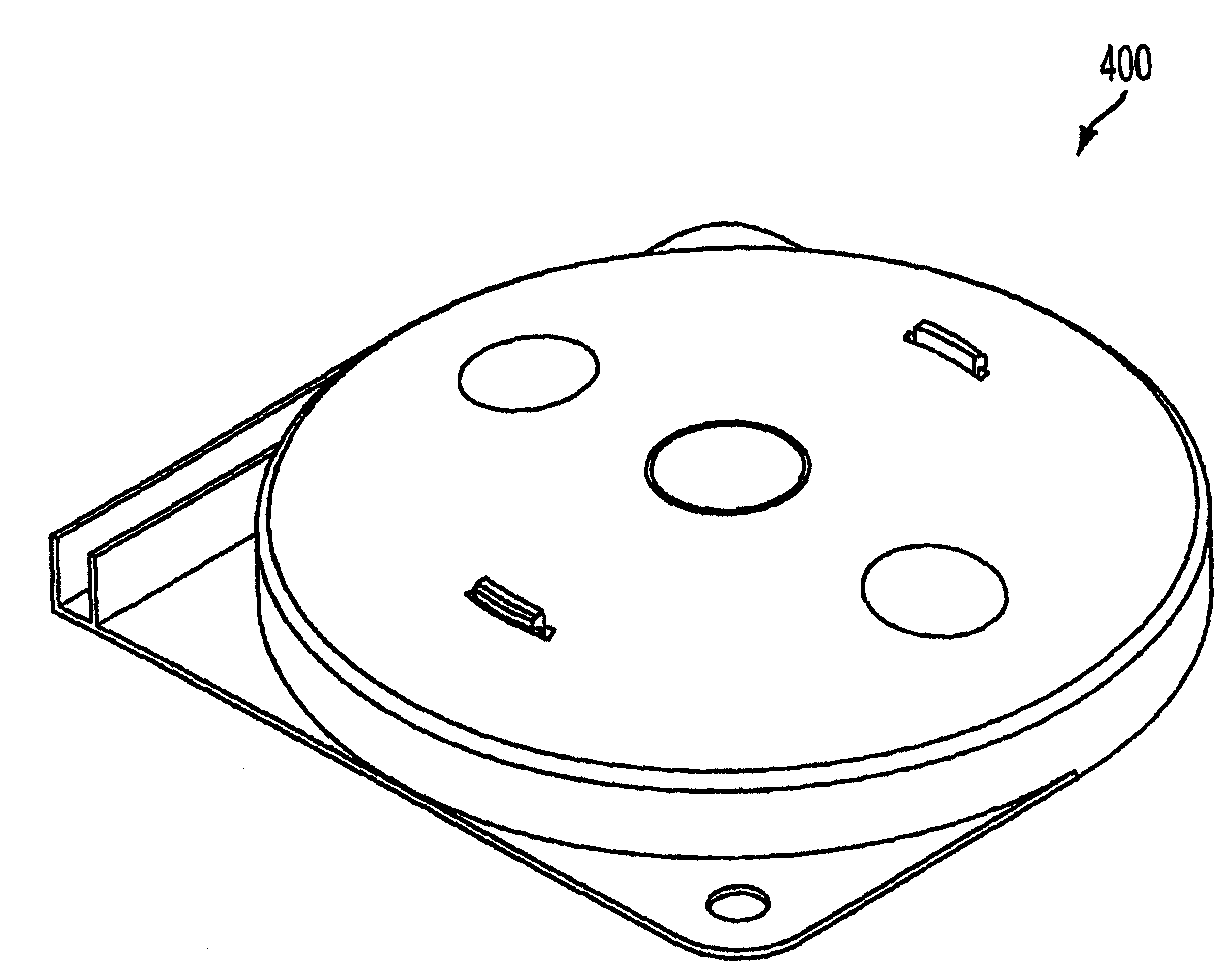
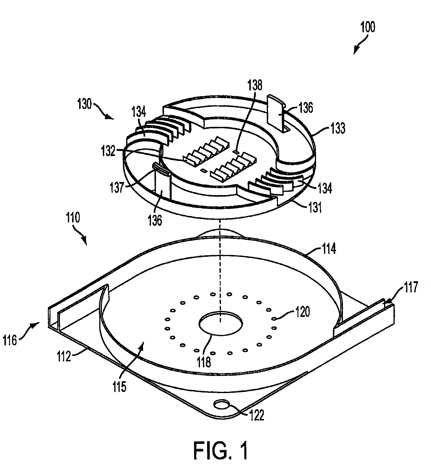
[0040]Turning now to FIG. 1, shown is a storage device 100 according to an exemplary embodiment of the present invention. The storage device 100 may be a storage tray or a splice storage tray. Storage device 100 includes a housing 110 and a rotating element 130. The ho...


PUM


Abstract

A storage device for storing cable or fiber, rotating element, and method of using the same are provided. The storage device includes a housing, having an inner cavity and at least one opening; and a rotating element which is rotatably and removably placed within the inner cavity and has at least one receptacle. The rotating element includes a base member; a receptacle for holding at least one splice sleeve containing a sliced fiber; and a plurality of guide ridges, which are disposed on the base member, one of the plurality of guide ridges disposed at either end of each of the at least one receptacle. The method includes placing the fiber or cable into the receptacle; draping excess fiber or cable through guide fins; and rotating the rotating element to retract or dispense the excess fiber or cable into or out of the storage device through the at least one opening in the housing.

Description

CROSS-REFERENCE TO RELATED APPLICATION[0001]This application claims the benefit of priority from U.S. Provisional Patent Application No. 60 / 703,504, filed in the U.S. Patent and Trademark Office on Jul. 29, 2005, the disclosure of which is incorporated herein by reference in its entirety.BACKGROUND OF THE INVENTION[0002]1. Field of the Invention[0003]Devices and methods consistent with the present invention relate to the storage of fibers in fiber optic communication systems, and more particularly, to the storage of excess fiber optic cable or ribbons in a fiber optic communication system.[0004]2. Description of the Related Art[0005]As the number of fibers deployed in fiber optic communication systems has increased, the management of fibers has become exceedingly complex. In splicing fibers, terminating fibers, and connecting fibers, each fiber typically has excess length which must be addressed. As the number of fibers increases, this excess length multiplies, causing problems in m...

Claims


Application Information

Patent Timeline
Patent Type & Authority Applications(United States)
IPC IPC(8): G02B6/00
CPCH01R13/72
Inventor HENDERSON, CRAIG
Owner AFL COMM LLC
Why Eureka
Try Eureka