Eureka AIR delivers breakthrough ideas for toughest innovation challenges, trusted by R&D personnel around the world.

Sash window assembly

Inactive Publication Date: 2008-08-28
YKK AP INC
View PDF0 Cites 1 Cited by
  • Summary
  • Abstract
  • Description
  • Claims
  • Application Information

AI Technical Summary

Benefits of technology

[0008]The present invention was achieved in view of the above-described problems, and it is an advantage thereof to provide a sash window assembly with which beads can be butted against one another at an angle and attached to a frame section with ease.
[0014]However, according to the sash window assembly of the invention, the bead is moved with the first engaging section inserted into the recess that is recessed toward the inner side of the frame section, thereby engaging the first engaging section with the frame section at the front-side in the movement direction; therefore, the position of the front end of the bead during this movement is located further toward the inner side of the frame section than the position of the front end of the bead after the bead has been attached to the frame section. Accordingly, even if two beads are already attached to the frame section so as to be adjacent to the bead that is to be attached, it is possible to allow for a space between the ends of the two already-attached adjacent beads and the bead that is to be attached when moving the bead in the depth direction. In addition, because there is a space between the bead that is to be attached and the ends of the adjacent beads, the rear-end side of the bead that is to be attached can be moved in the direction away from the second engaging projection, and the bead can therefore be tilted. Furthermore, by moving the bead that is to be attached into the space between the adjacent beads in the tilted state, the second engaging section can be moved further toward the front-side in the movement direction than the second engaging projection without the second engaging section coming in contact with the second engaging projection. When the second engaging section is moved further to the front-side in the movement direction than the second engaging projection, the first engaging section and the first engaging projection are engaged with one another, and when the bead is rotated so that the second engaging section moves in the direction that brings it closer to the frame section, the second engaging section and the second engaging projection are engaged with one another, making it possible to attach the bead with ease, even if the bead has ends that are angled and that butt up against one another.
[0018]According to such a sash window assembly, the rotation limiting projection piece makes contact with the second engaging projection by the second engaging section and the second engaging projection engaging with one another. Therefore, when attaching the bead, the rotation of the bead in the direction that brings the second engaging section closer to the frame section is limited, which maintains the state in which the movement limiting projection piece makes contact with the second engaging projection, making it possible to attach the bead to the frame section in a state where it is even more difficult for the bead to become detached.
[0020]According to such a sash window assembly, the movement limiting projection piece and the rotation limiting projection piece are pressed upon the second engaging projection with the elastic sealant provided between the face material and the bead. Therefore, the bead is pressed so that movement in the direction opposite to the movement direction when attaching the bead, and rotation in the direction in which the second engaging section moves away from the frame section, are both limited, making it possible to attach the bead to the frame section in a state where it is even more difficult for the bead to become detached. At this time, reactive force arises between the sealant and the face material, making it possible to securely hold the face material in place.
[0021]According to the present invention, it is possible to provide a sash window assembly with which beads can be butted against one another at an angle and attached to a frame section with ease.

Problems solved by technology

However, the beads used in the above-mentioned conventional fixed window are problematic.
First, the vertical beads cannot be removed unless the upper bead is unfastened and then moved in the upper direction.
Furthermore, the upper bead is unfastened when removing the vertical beads, and thus the upper bead is required to be supported somehow in the upward direction, resulting in a complicated procedure for removing the bead.
For this reason, it is difficult to attach the four beads that support all sides of the face material to the four frame elements by moving the beads along the surface of the face material, from the center side of the face material toward the inner sides of the frame sections.
However, when two beads adjacent to the bead that is to be attached are already attached, and the fourth bead is to be attached between these adjacent beads, the ends of the fourth bead make contact with the ends of the beads that are already attached, and thus cannot be attached.
Therefore, when attaching the bead, the movement of the bead toward the rear-side in the movement direction is limited, making it possible to attach the bead to the frame section in a state where it is difficult for the bead to become detached.
Therefore, the bead is pressed so that movement in the direction opposite to the movement direction when attaching the bead, and rotation in the direction in which the second engaging section moves away from the frame section, are both limited, making it possible to attach the bead to the frame section in a state where it is even more difficult for the bead to become detached.

Method used


Image

  • Sash window assembly
  • Sash window assembly
  • Sash window assembly

Examples


Embodiment Construction

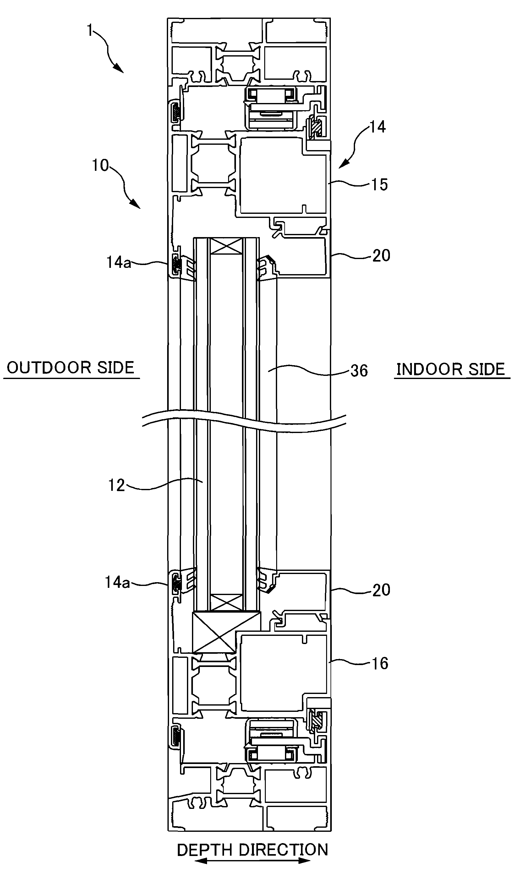
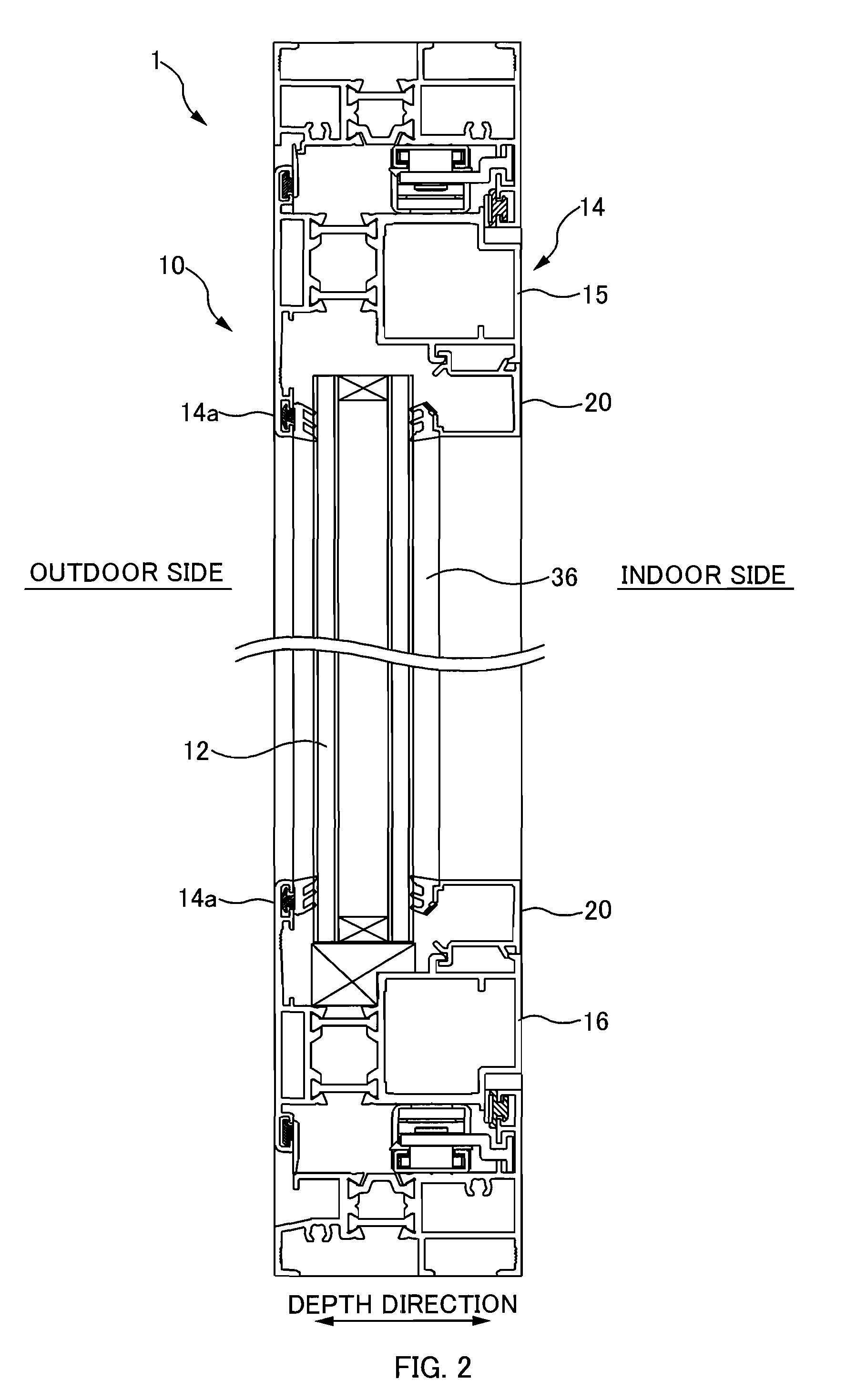
[0030]At least the following matters will be made clear by the explanation in the present specification and the description of the accompanying drawings.

[0031]A sash window assembly according to an embodiment of the invention shall be described hereinafter with reference to the drawings.

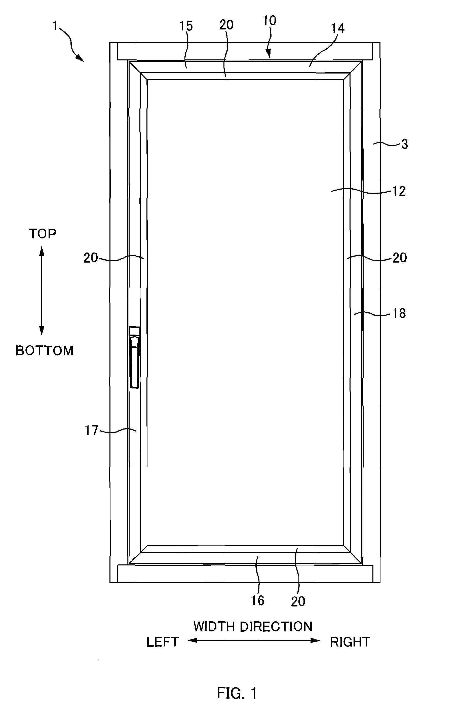
[0032]The present embodiment describes, as an example, a sash window assembly in which sashes are supported so as to be rotatable within a sash frame provided in an opening section that is open between an indoor side and an outdoor side, thereby making the area within the sash frame openable / closable, as shown in FIG. 1.

[0033]In the following descriptions, the direction that appears vertical when a sash window assembly 1 is viewed from the indoor side shall be referred to as the “vertical direction”; the direction that appears horizontal shall be referred to as the “horizontal direction” or a “width direction”; and the direction spanning between an indoor side and an outdoor side shall be referred to...


PUM


Abstract

A sash window assembly includes a face material provided in an opening section open to an indoor and outdoor side, a frame section provided within the opening section, and beads attached to the frame section with the ends of the beads angled and butted against one another, the beads for pressing upon the face material from one of the indoor and outdoor directions, wherein each of the beads includes a first engaging section and a second engaging section, the first engaging section engaging with the frame section at a front-side in a movement direction, the second engaging section engaging with the frame further toward a rear-side in the movement direction than the first engaging section, when the bead is moved in the movement direction along a depth direction; the frame section includes a first engaging projection that engages with the first engaging section, a second engaging projection that engages with the second engaging section, and a recess provided between the first engaging projection and the second engaging projection, the recess being recessed toward an inner side of the frame section; and each of the beads is moved with the first engaging section of each bead inserted into the recess, the first engaging section being engaged with the first engaging projection in a state where the bead is tilted so that the second engaging section moves away from the frame section, the second engaging section being engaged with the second engaging projection by rotating the bead in a direction that brings the second engaging section closer to the frame section.

Description

CROSS-REFERENCE TO RELATED APPLICATIONS[0001]The present application claims priority upon Japanese Patent Application No. 2007-042436 filed on Feb. 22, 2007, which is herein incorporated by reference.BACKGROUND[0002]1. Technical Field[0003]The present invention relates to a sash window assembly, and particularly relates to a sash window assembly including a face material provided in an opening section that is open to an indoor side and an outdoor side, a frame section provided within the opening section, and beads attached to the frame section with the ends of the beads angled and butted against one another.[0004]2. Related Art[0005]A sash window assembly including a face material provided in an opening section that is open to an indoor side and an outdoor side, a frame section provided within the opening section, and beads attached to the frame section with the ends of the beads angled and butted against one another, is known. This sash window assembly is found in a fixed window, i...

Claims


Application Information

Patent Timeline
IPC IPC(8): E06B3/96E06B1/04
CPCE06B3/5821
Inventor FUJII, TAKERU
Owner YKK AP INC
Why Eureka
Eureka Blog
Learn More