
Upsetting method and upsetting apparatus

a technology of upsetting apparatus and upsetting method, which is applied in the direction of manufacturing tools, forging/pressing/hammering apparatus, and shaping tools, etc., can solve the problems of poor shape of manufactured products and degradation in value as a product, and achieve the effect of reducing molding pressure, reducing deformation resistance, and efficient diameter expansion working

Inactive Publication Date: 2008-08-28
RESONAC HOLDINGS CORPORATION
View PDF3 Cites 30 Cited by
  • Summary
  • Abstract
  • Description
  • Claims
  • Application Information

AI Technical Summary

Benefits of technology

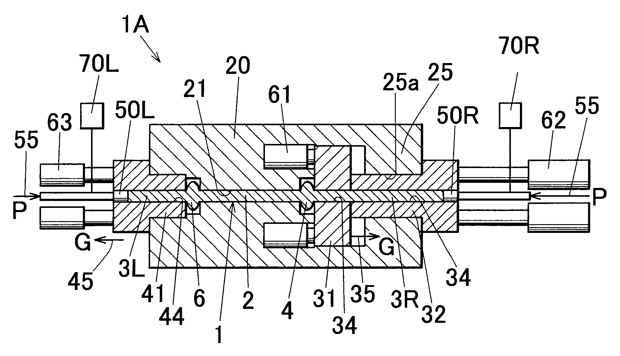
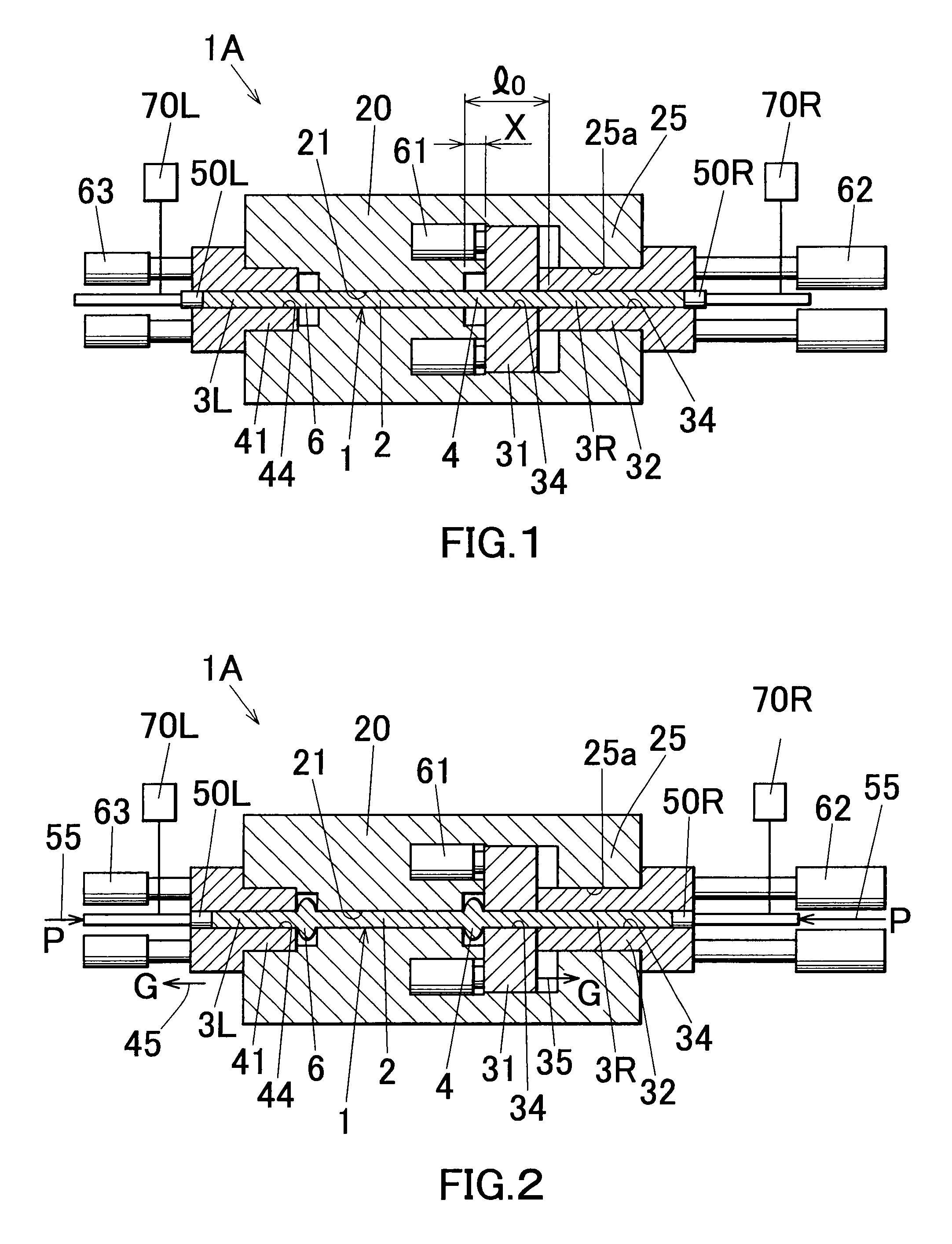
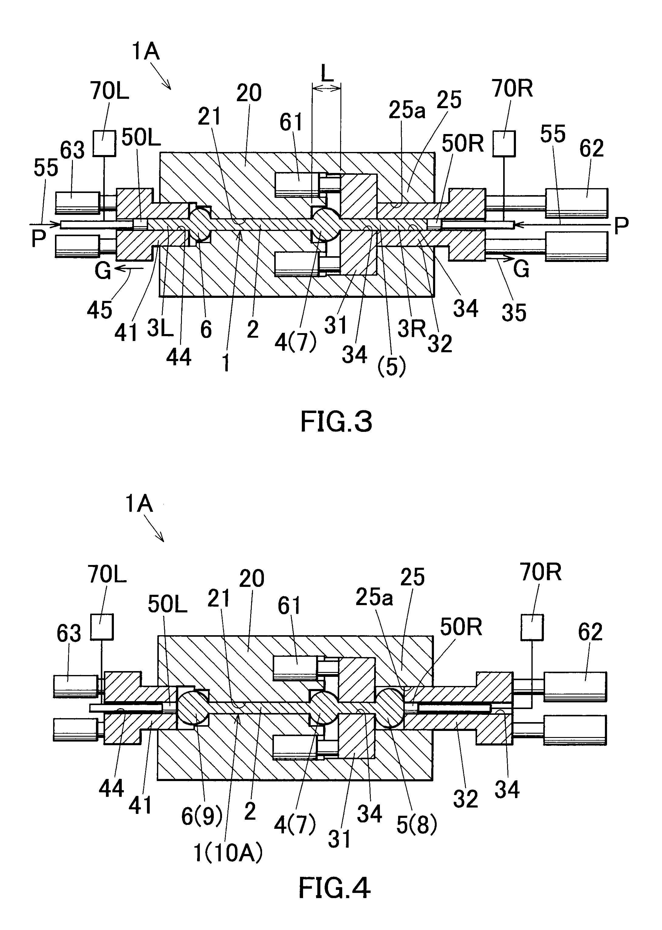
[0128]According to the invention as recited in the aforementioned Item [1], at least two portions (the first exposed portion and the second exposed portion) of the raw material can be expanded in diameter without requiring the reversing of the raw material. Therefore, in expanding two or more portions of the raw material by the upsetting, the diameter expansion working can be performed efficiently.
[0129]According to the invention as recited in the aforementioned Item [2], since the exposed portion of the raw material is expanded in diameter in a non-restrained manner, the exposed portion can be expanded in diameter by a low punch pressing force, i.e., a low molding pressure, which in turn can reduce the driving force for driving the punch. Furthermore, since the exposed portion can be expanded in diameter without using an expensive forming die having a molding dented portion, the manufacturing cost, i.e., working cost, can be reduced. Furthermore, when the average moving speed G from the moving initiation of the guide satisfies the prescribed relational expression, the buckling which may sometimes cause at the time of working can be prevented assuredly.
[0130]According to the invention as recited in the aforementioned Item [3], the exposed portion of the raw material can be assuredly expanded in diameter into a designed shape.
[0131]According to the invention as recited in the aforementioned Item [4], the removal of the upsetting manufactured product from the guide insertion hole can be performed without problem after the completion of the working.
[0132]According to the invention as recited in the aforementioned Item [5], since the round bar-shaped raw material made of a rolled material can be obtained or manufactured at low cost, the working cost can be reduced by using this raw material as a raw material for the upsetting.
[0133]Furthermore, this material is poor in circularity as compared with a round bar-shaped raw material made of an extruded material. Therefore, when this raw material is inserted into the insertion hole of the guide, a gap will be inevitably generated between the surface of the raw material and the peripheral surface of the insertion hole. Thus, the contact-surface area therebetween is small. Therefore, since the frictional-resistance force at the time of slidably moving the raw material in the insertion hole of the guide in the axial direction is small, the molding pressure can be reduced. Therefore, as a punch driving apparatus for moving the punch, a small one can be used, enabling space-saving of an installation space for the upsetting apparatus.

Problems solved by technology

In this upsetting, if a material buckles at the time of the working, the obtained product (upsetting manufactured product) becomes poor in shape (e.g., wrinkles, scratches, etc.), which causes degradation in value as a product.

Method used


Image

  • Upsetting method and upsetting apparatus
  • Upsetting method and upsetting apparatus
  • Upsetting method and upsetting apparatus

Examples


examples

[0420]Next, concrete examples of the present invention are shown below. However, the present invention is not limited to the following examples.

[0421]A round bar-shaped raw material 1 made of a continuously cast rolled material having a diameter of 12 mm manufactured by a Properzi method, and a round bar-shaped raw material 1 made of an extruded material having a diameter of 12 mm were prepared. The material of each of the raw materials 1 is a JIS (Japanese Industrial Standards) A6061 aluminum alloy. These raw materials 1 were subjected to upsetting using the upsetting apparatus 10C of the third embodiment. The molding pressure required at the upsetting was checked. The results are shown in Table 1.

TABLE 1Type of rawHeatingHeatingMoldingmaterialmodetemperatureCoolingpressureExample 1RolledPartial500° C.Yes4.4 × 107 PamaterialheatingExample 2RolledEntire400° C.No7.5 × 108 PamaterialheatingExample 3ExtrudedPartial500° C.Yes7.1 × 107 PamaterialheatingExample 4ExtrudedEntire400° C.No8.2...


PUM


Abstract

To provide an upsetting method capable of efficiently expanding a bar-shaped raw material at least two portions. A plurality of guides 31 and 32 each having an insertion hole 34 are prepared. The bar-shaped raw material 1 secured to a fixed die 20 is inserted and held in each insertion hole 34 of the plurality of guides 31 and 32 in order. Then, a first exposed portion 4 of the raw material 1 exposed between a first guide 31 located at the foremost side of the plurality of guides 31 and 32 and the fixed die 32 is expanded in diameter by moving the plurality of guides 31 and 32 in a direction opposite to a moving direction of the punch 50R in a mutually adhering manner while pressurizing the raw material 1 in the axial direction with the punch 50R. After completion of the movement of the first guide 31, a second exposed portion of the raw material 1 exposed between both the guides 31 and 32 is expanded in diameter by relatively moving the second guide 32 located behind the first guide 31 among the plurality of guides 31 and 32 in a direction opposite to a moving direction of the punch 50R.

Description

CROSS REFERENCE TO RELATED APPLICATIONS[0001]The present application is a division of application Ser. No. 11 / 342,650, filed on Jan. 31, 2006, which claims priority to Japanese Patent Application No. 2005-24178 filed on Jan. 31, 2005, and U.S. Provisional Application No. 60 / 649,547 filed on Feb. 4, 2005, the entire disclosures of which are incorporated herein by reference in their entireties.FIELD OF THE INVENTION[0002]The present invention relates to an upsetting method and an upsetting apparatus for radially expanding two or more portions of a bar-shaped raw material.DESCRIPTION OF THE RELATED ART[0003]In general, upsetting is executed to expand a diameter of a certain portion of a material by pressurizing a bar-shaped raw material in an axial direction thereof. In this upsetting, if a material buckles at the time of the working, the obtained product (upsetting manufactured product) becomes poor in shape (e.g., wrinkles, scratches, etc.), which causes degradation in value as a pro...

Claims


Application Information

Patent Timeline
Patent Type & Authority Applications(United States)
IPC IPC(8): B21D31/00B21D37/16B21D41/02
CPCB21J5/08
Inventor OTAKI, ATSUSHI
Owner RESONAC HOLDINGS CORPORATION
Learn More