Double flame perimeter burner

a burner and perimeter technology, applied in the direction of combustion ignition, heating fuel, combustion process, etc., can solve the problems of no burner, insufficient thermal capacity of fixed predetermined areas for cooking,

Inactive Publication Date: 2008-08-28
MABE MEXICO S DE R L DE
View PDF9 Cites 34 Cited by
  • Summary
  • Abstract
  • Description
  • Claims
  • Application Information

AI Technical Summary

Benefits of technology

[0015]Therefore, an object of the present invention is providing a burner assembly which includes at least two different burners in the same axis, for better cooking and heating of the user's food.
[0016]A further object of the invention is providing sufficient thermal capacity to heat or cook in a uniform manner the contents of the crock, griddle or similar, that has a greater dimension to that of a fixed cooking area.
[0017]Yet a further object of the invention is providing burners having cooperation amongst themselves, allowing the user to select the burners to be used, and the quantity of burners to be used.
[0018]A further object of the invention is that a predetermined distance between the main burner and the secondary burner in regards to a third burner exists, so that the flames of the burners have no interference.
[0020]Another object of the invention is providing burners that have cooperation amongst themselves, and that said burners are easy to produce, assemble, clean and give maintenance to.

Problems solved by technology

One of the problems found in current ranges, grates, stoves, grills, cookers or cook-tops, is that they have fixed predetermined areas for cooking by means of fixed burners, the user selecting between said fixed predetermined areas which of the burners will be used.
Another problem found in current ranges, grates, stoves, grills, cookers or cook-tops, is that said fixed predetermined areas for cooking are not provided with sufficient thermal capacity to heat or cook in a uniform manner a crock, griddle or other cooking utensil, that has a greater dimension than the burning area of the burner, and thus the crock, griddle or other cooking utensil has to be rotated and moved.
A further problem found in current ranges, grates, stoves, grills, cookers or cook-tops, is that there are no burners having cooperation amongst themselves, allowing the user to select the burners to be used and the quantity of burners to be used.

Method used


Image

  • Double flame perimeter burner
  • Double flame perimeter burner
  • Double flame perimeter burner

Examples


first embodiment

of the Invention

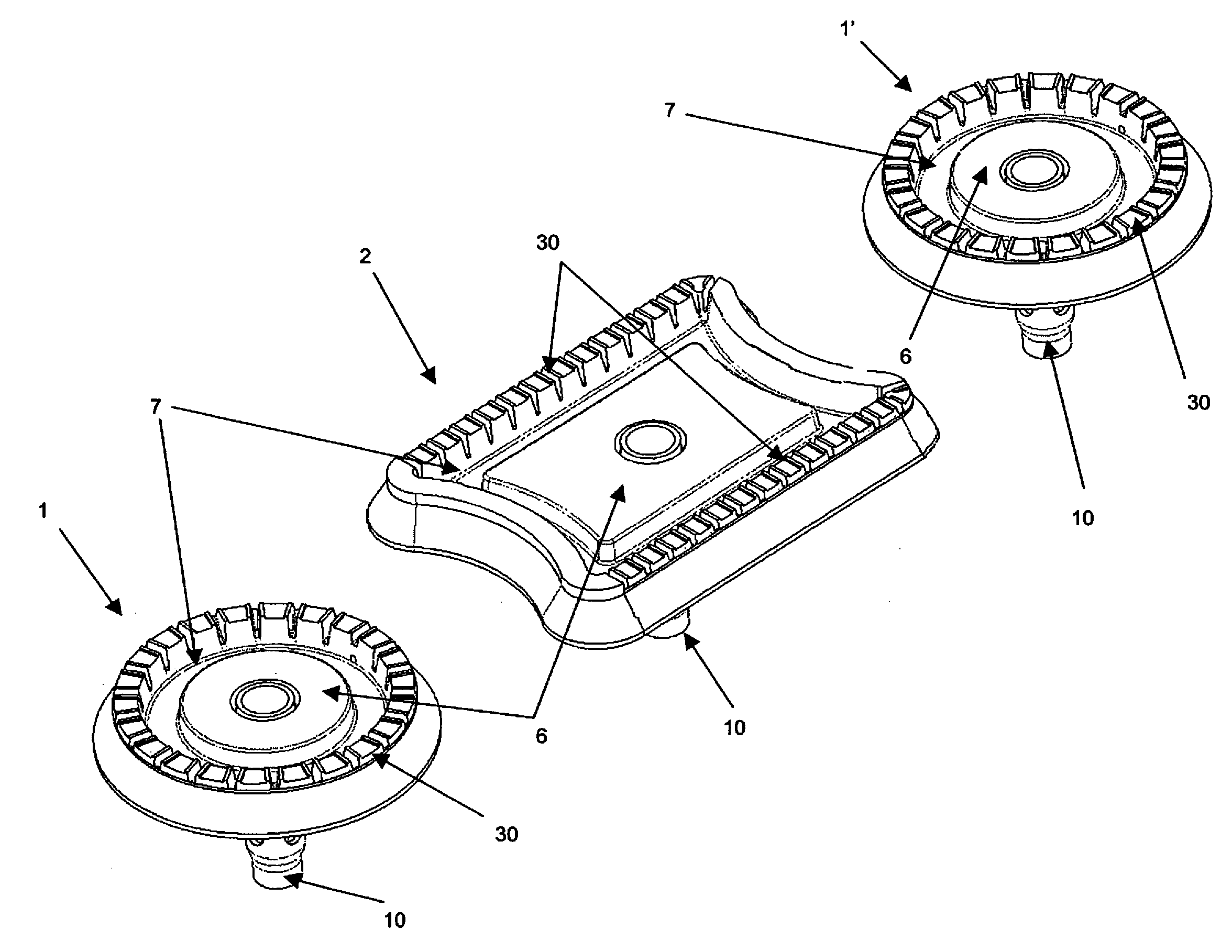
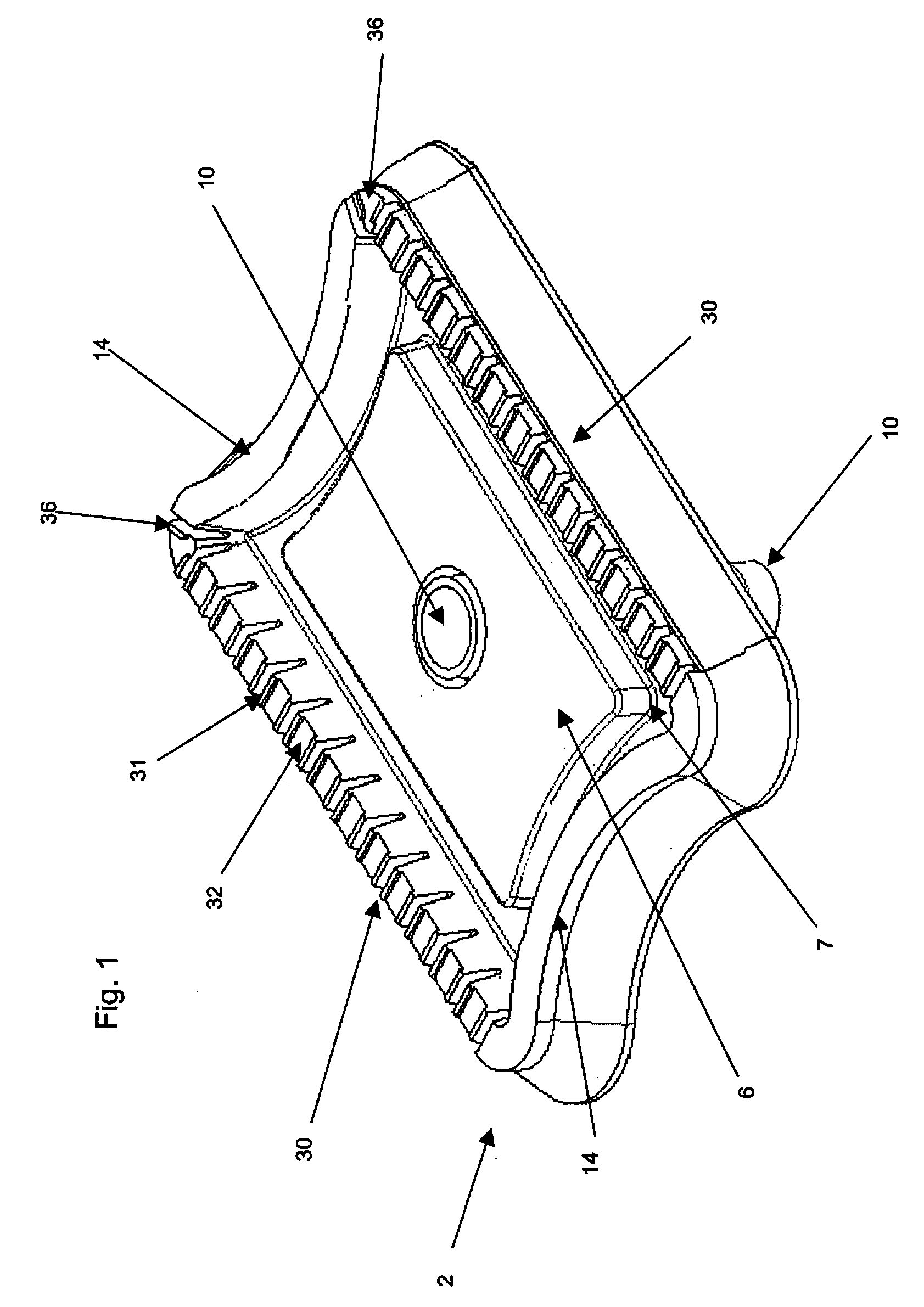
[0049]FIG. 1 shows an isometric superior view of the satellite burner 2 of the present invention, said burner has a semi-rectangular form, showing in its longer sides port zone 30 longitudes. In its perpendicular sides, the satellite burner 2 has a neck 14 or an arc segment, to cooperate in its ends with the main burners 1, which preferably have a round geometry.

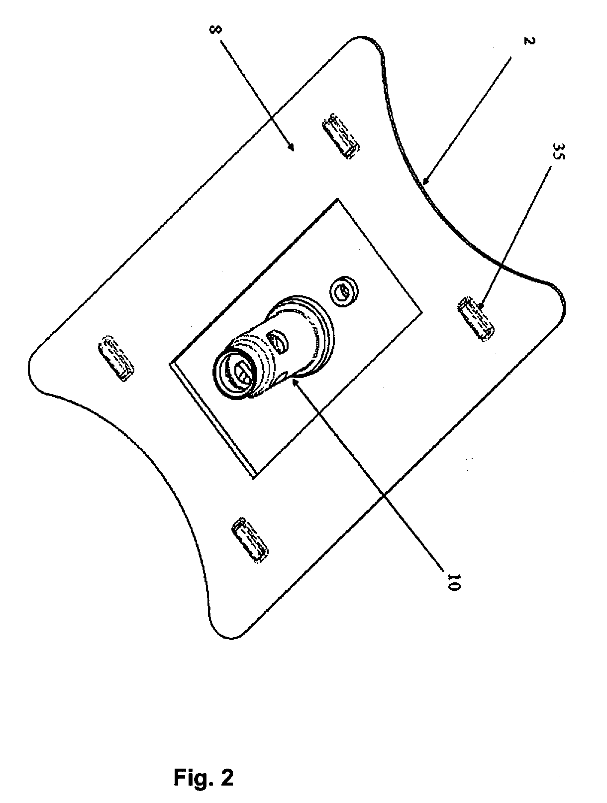
[0050]As appreciated in FIG. 3a, a mixer or Venturi tube 10 allowing the fuel gas mix, coming from flow regulating valves 15, to be directed to a nozzle 16, which reduces the pressure and allows a determined flow velocity. The mixer tube 10 embraces the nozzle 16 by means of a throat 19, which may be above said nozzle 16, so that the flow coming from the nozzle 16 may be introduced to the mixer tube 10, generating a Venturi effect dragging the air around, introduced by the windows 18. The mixer tube 10 has a regulating ring (not shown), which restricts the air pass to the interior of the mixer tube 10, to mod...

second embodiment

of the Invention

[0066]FIG. 8 shows a second embodiment of the burner of the present invention. Main burner 1 has modified its form to a kind of horse-shoe. Over the periphery of this horse-shoe the port zone 30 is found. Once moved the circular form of the main burner 1 to this new horse-shoe form, we shall call this burner to distinguish it as horse-shoe main burner 5. When fusing the horse-shoe main burner 5 with the secondary burner 2, a body 37 is obtained, with semi-rectangular form in the front of two burners 5, 2 and with the lateral ends in semicircular form.

[0067]The horse-shoe main burner 5 and the satellite burner 2, are fused in the same body 37, having an advantage when both burners 5, 2 are assembled, produced, maintained and installed.

[0068]In a descriptive however not limitative manner, a port design as was disclosed for the before embodiment may be considered. As shown in FIG. 8, the arc segment 14 of the satellite burner 2 does not have ports, thus no flame is emit...

third embodiment

of the Invention

[0072]With the fusion of both burners in a single body 37, a main burner 1 and a satellite burner are joined again in a single body, providing the advantages of: manufacture, assembly, maintenance and less part numbers to handle.

[0073]The main burner 1 and the satellite or secondary burner 2, are cinched in a single base 38, wherein the fused main burner 1 will be called circumcised main burner 21. As seen in FIGS. 11 and 11a, said circumcised main burner 21 retains its port zone 30, spark 20, plateau 6, chamber 7 and cap 11, with the peculiarity of being joined to the satellite burner by means of a base 38, allowing having both burners 21 and 2 contained in a single piece. Therefore, the secondary burner 2 also retains its port zone 30, plateau 6, chamber 7, cap 12 and a pair of flame transfer ports 36 in its ends of the port zone 30 closest to the circumcised main burner 21, such as was disclosed for the first embodiment of the invention. Said description is here a...


PUM


Abstract

A burner for range covers or similar, to allow a broad range of calorific capacities, and a better burner distribution in the cover, with a generally semi-rectangular form, and containing a plurality of ports and a plurality of manners to ignite it, wherein the burner is capable of interacting with other burners at determined length and height distances, creating discontinuous flames between the burners.

Description

FIELD OF THE INVENTION[0001]The invention refers to systems and apparatus for cooking in general, such as range, grills, grates, cookers or cook tops or similar, and in a more specific manner to conventional burners with or without bridges to provide a variety of heating configurations according to the necessities of the operator of the range, grate, stove, grill, cooker or similar.BACKGROUND OF THE INVENTION[0002]Range, grate, stove, grill, cooker or cook tops covers that include one or more burners in the same axis are known in the art. It is common that a main burner may have a maximum thermal capacity of about 4,229 kilojoules (4,000 BTU) to about 10,600 kilojoules (10,000 BTU) an hour in its highest position. The minimum thermal capacity of a burner may be reduced to about 633 kilojoules (600 BTU) an hour without flame extinguishment. It is logical that the ring diameter of the flame, determines the heat output coefficient of the burner.[0003]A higher output coefficient, may be...

Claims


Application Information

Patent Timeline
Patent Type & Authority Applications(United States)
IPC IPC(8): F24C3/08F23D14/62F23Q1/00
CPCF23D14/58F23D14/06
Inventor CALOCA GALINDO, VICTOR GERARDOSANTOYO, JOSE ARTURO LONABOTELLO, ROBERTO CABRERA
Owner MABE MEXICO S DE R L DE
Why Eureka
Try Eureka