Thermally managed LED recessed lighting apparatus

a led lighting and recessed technology, applied in lighting and heating apparatus, lighting support devices, lighting applications, etc., can solve the problems of increasing increasing the difficulty of installation, and particularly challenging applications, and achieves low thermal resistance, high heat carrying capacity, and the effect of avoiding shortening the life of the led

Inactive Publication Date: 2011-03-17
WYNDSOR LIGHTING
View PDF31 Cites 79 Cited by
  • Summary
  • Abstract
  • Description
  • Claims
  • Application Information

AI Technical Summary

Benefits of technology

[0016]This structure provides a thermal path having low thermal resistance and high heat carrying capacity that substantially directly thermally couples the LED to the exterior of the trim where it can liberated to the ambient environment in sufficient quantities and at a sufficient rate to not only maintain the housing at suitably low safe temperature to avoid a fire hazard but also to keep the operating temperature of the LED within its maximum rating and thereby avoid

Problems solved by technology

Such applications can be particularly challenging, even with fixtures using conventional lamps, since little free space or convective circulation may be available within the confines of the niche to adequately cool the fixture.
They are made even more difficult if one wishes to meet the needs of applications in which it would not be possible, or would be undesirable, to provide the trim with vents capable of permitting substantial convective flow to take place through the aperture or other parts of the trim, to transfer heat by convection from the housing to the ambient environment which interfaces with the exterior of the trim.
They are made more challenging still if one wishes to address such applications while at the same time providing energy savings which are offered by using energy efficient light emitting diodes as a light source rather than an incandescent bulb or other conventional lamp.
However, it is not a process which results in 100% conversion of electrical energy into light.
If sufficient amounts of heat are not carried away from the area of the p-n junction at a sufficient rate, it will cause the operating temperature of the LED to rise to an unacceptably high temperature which

Method used


Image

  • Thermally managed LED recessed lighting apparatus
  • Thermally managed LED recessed lighting apparatus
  • Thermally managed LED recessed lighting apparatus

Examples


Embodiment Construction

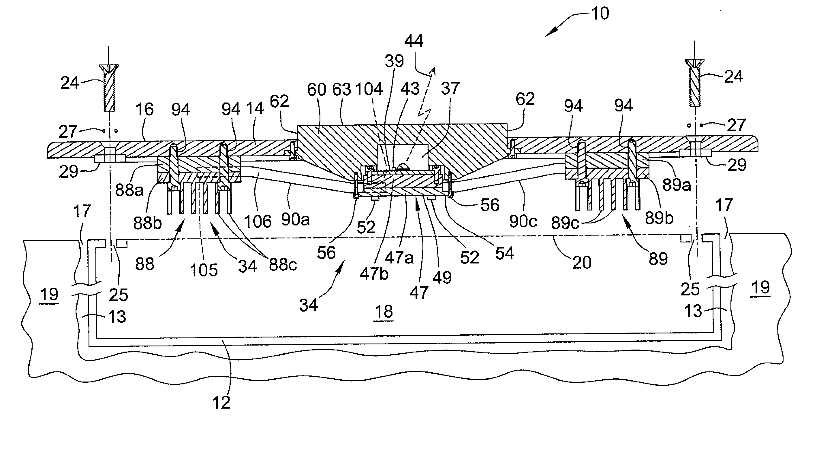
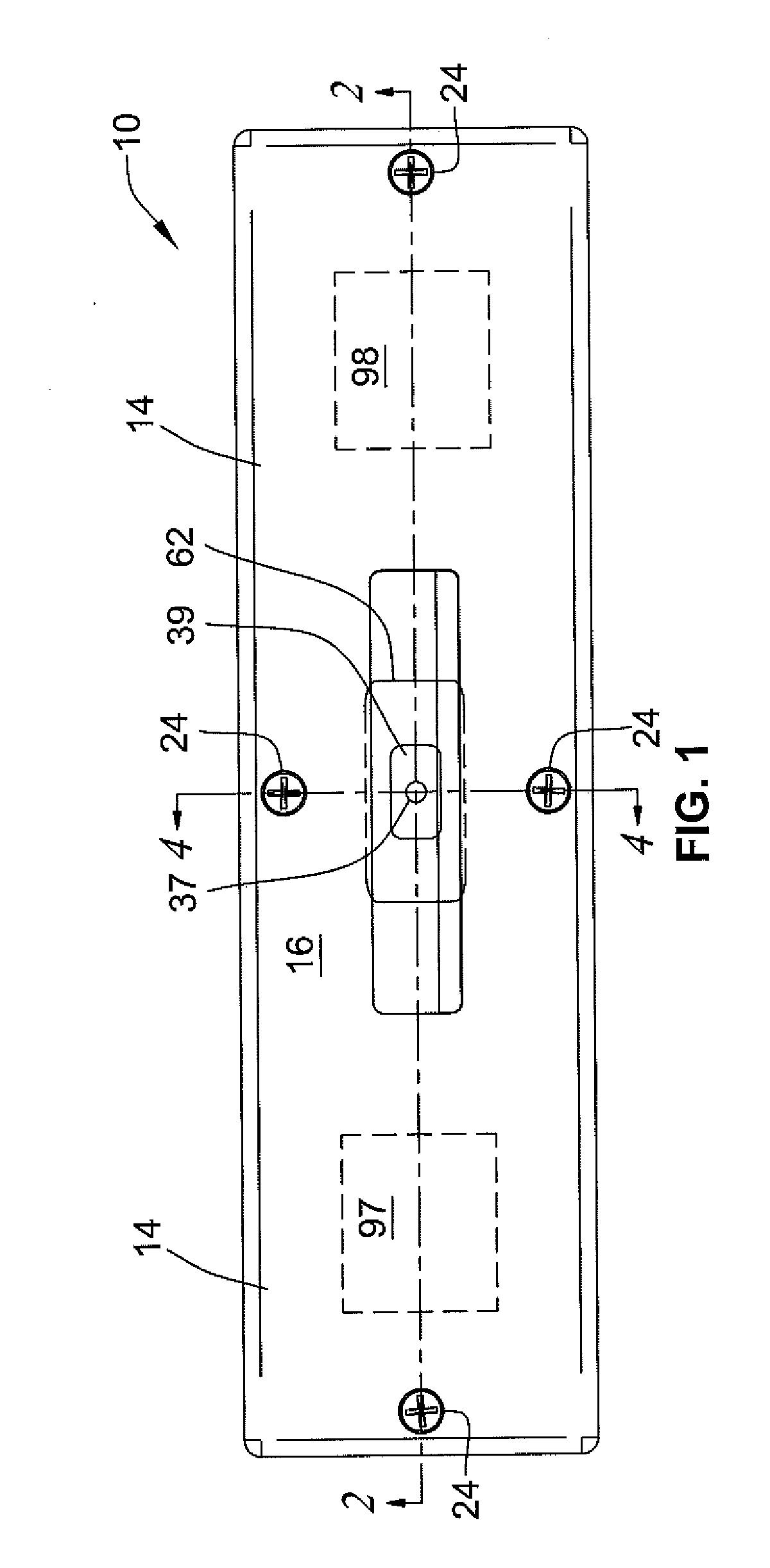
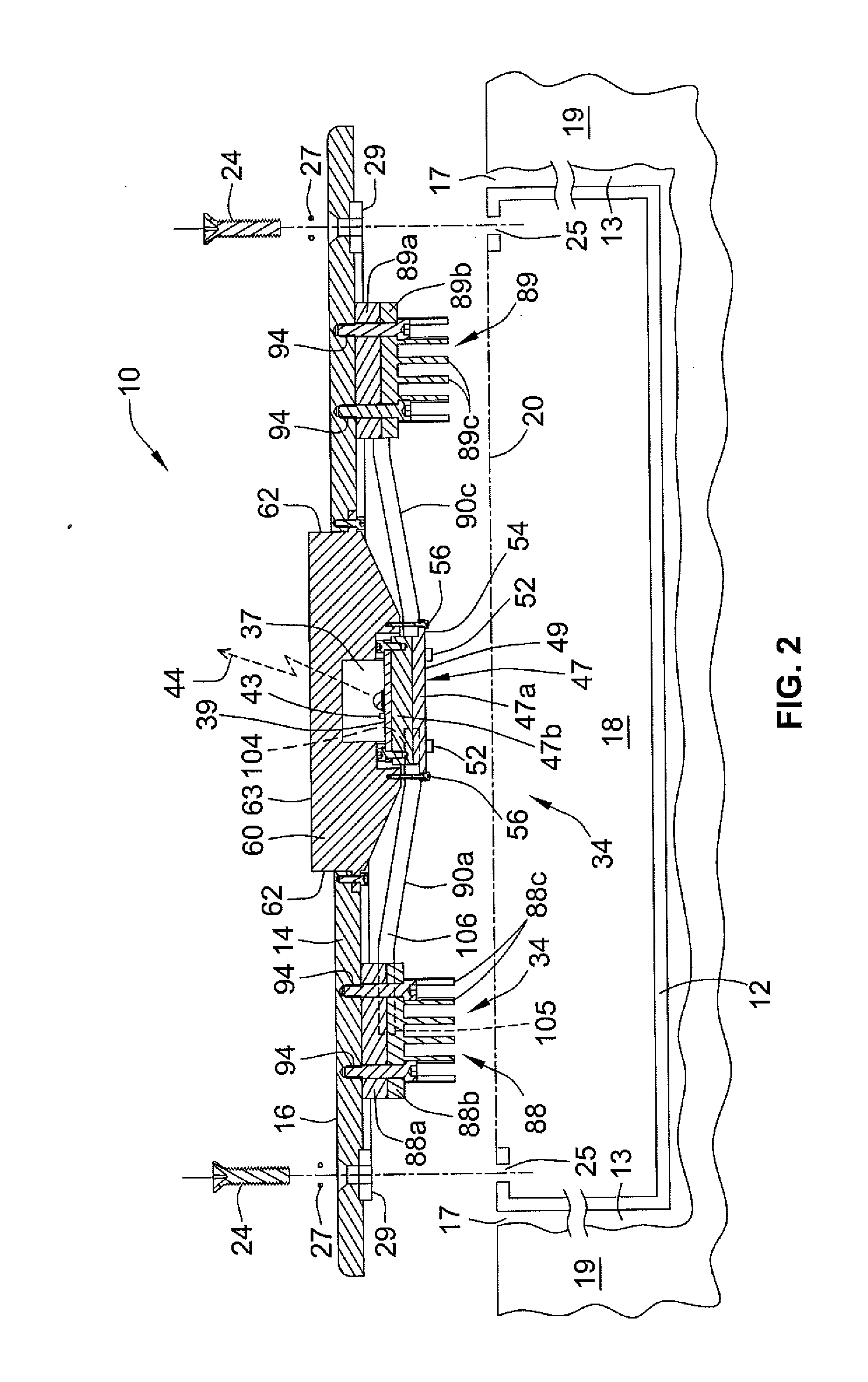
[0023]Referring collectively to FIGS. 1 through 4, a preferred embodiment of a thermally managed LED lighting apparatus 10 constructed according to the present invention includes a housing 12, and a trim which comprises a non-vented trim 14. The housing 12 mounts in a recess 13 located behind a recess opening 17 formed in an architectural structure 19. By way of non-limiting example, architectural structure 19 may be a wall, ceiling, stair riser, pool, fountain, water feature, or bollard and may be located either indoors or outdoors, above water or below. The trim, namely non-vented trim 14, trims the recess opening 17 and generally conceals all or most of housing 12 and the edge(s) of the recess opening 17 after trim 14 is installed.

[0024]Trim 14 has an inside surface 15 and a substantially planar outside surface 16. The housing 12 at least partially encloses an interior space 18 within housing 12 and has a front opening 20 adjoining interior space 18. The non-vented trim 14 is sec...


PUM


Abstract

An LED recessed lighting apparatus has a housing mountable in a recess located behind a recess opening in an architectural structure. A non-vented trim is securable in place over the recess opening. A lens that allows light from the LED to pass through the trim has a fluid-tight internal cavity containing at least the light-emitting portion of the LED. At least a major portion of the heat generated by the LED is carried directly from the LED to the outside surface of said trim by way of a thermal path that includes a first heat sink located substantially immediately adjacent and intimately thermally conductively coupled to the LED, at least one second heatsink supported by and substantially directly thermally conductively coupled to, the inside of the trim, and at least one heat pipe thermally connecting the first heat sink to the second heat sink.

Description

CROSS-REFERENCE TO RELATED APPLICATIONS[0001]Not Applicable.STATEMENT REGARDING FEDERALLY SPONSORED-RESEARCH OR DEVELOPMENT[0002]Not Applicable.INCORPORATION BY REFERENCE[0003]Not Applicable.FIELD OF THE INVENTION[0004]The invention relates to the field of recessed lighting fixtures, luminaires, and lighting modules for general illumination or architectural illumination of indoor or outdoor areas using light emitting diodes (LED's). More particularly, the invention relates to a thermally managed recessed LED lighting apparatus having a trim and a fluid-tight LED module which are thermally coupled to one another by way of a thermal management pathway through which at least a major portion of the steady state thermal burden generated by the LED illumination source can be off-loaded from the trim to the exterior ambient environment without need of providing ventilation through or behind the trim to avoid causing a fire hazard and / or shortening the operating life expectancy of the LED d...

Claims


Application Information

Patent Timeline
IPC IPC(8): F21V5/00F21S4/00
CPCF21S8/02F21V5/04F21V29/004F21W2131/10F21Y2101/02F21V29/763F21V31/04F21V23/005F21W2121/02F21W2131/401F21Y2105/008F21V29/006F21Y2105/00F21Y2115/15F21Y2115/10F21V29/51F21V29/717
Inventor COOK, WILLIAM V.
Owner WYNDSOR LIGHTING
Why Eureka
Try Eureka