
Blade server

a server and blade technology, applied in the field of blade servers, can solve the problems of large power requirements of high-performance processors, and achieve the effects of reducing the cost and maintenance overhead associated with the provision of such centralised uninterruptible power supplies, more power efficient processors, and higher power density batteries

Inactive Publication Date: 2010-11-25
ARM LTD
View PDF9 Cites 79 Cited by
  • Summary
  • Abstract
  • Description
  • Claims
  • Application Information

AI Technical Summary

Benefits of technology

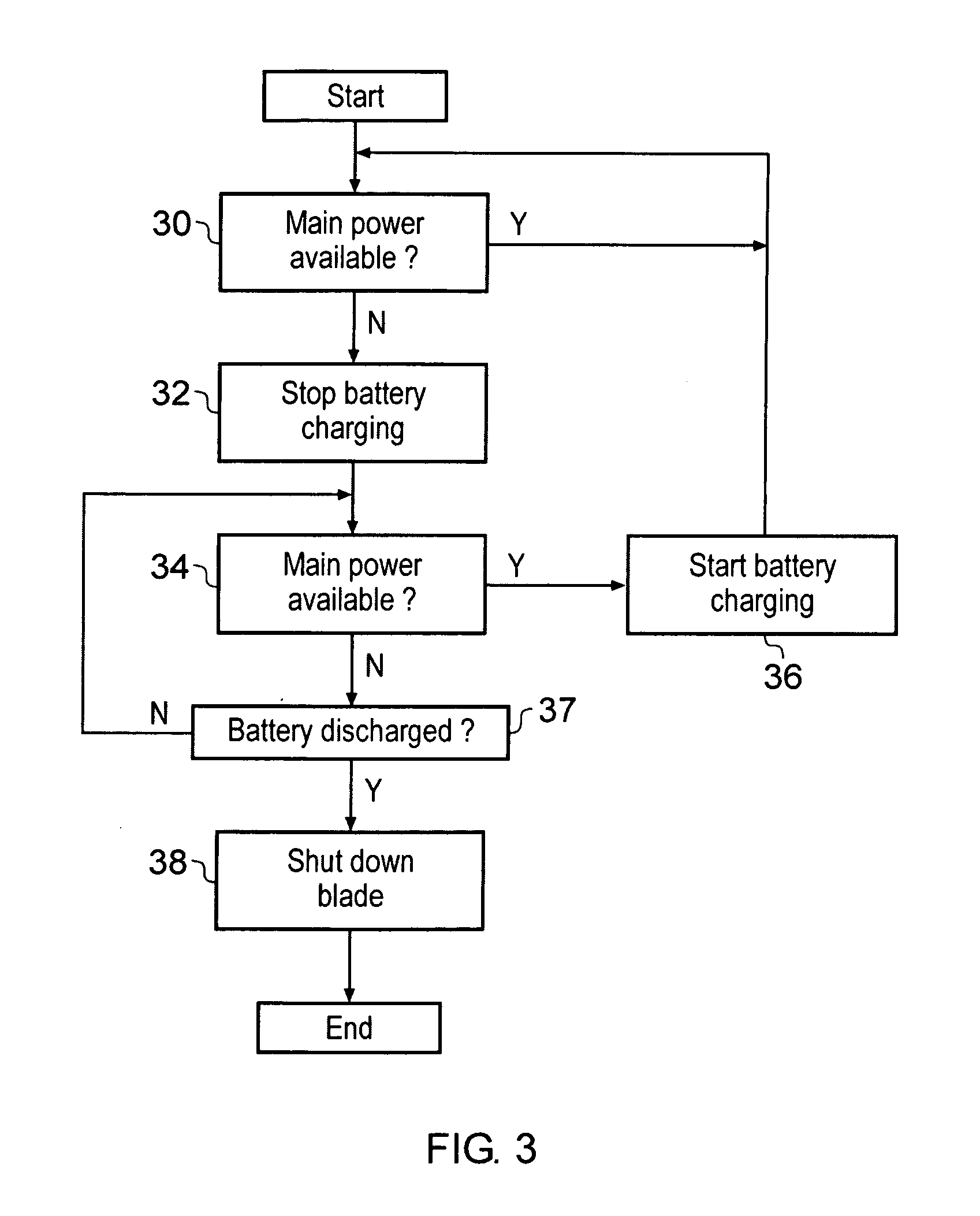
[0012]The present technique recognises that with the advent of more power efficient processors and higher power density batteries it becomes possible to provide blade servers with an on-board backup battery power supply. While this might initially seem counter to the normal design trend within this field whereby a single large, complex and capable uninterruptible power supply is provided and shared by a plurality of blade servers, the present technique provides a number of advantages. One advantage is that the cost and maintenance overhead associated with the provision of such centralised uninterruptible power supplies is reduced. Further, the on-board nature of the backup power supply provided to the blade server tends to make it more reliable; providing separate backup power supplies to each of the blade servers means that, if one of these backup power supplies is defective, then it need only impact the individual blade server whereas if a centralised uninterruptible power supply is defective then this can render inoperative a large number of blade servers with severe consequences. The configuration and testing of uninterruptible power supplies requires labour and ongoing effort. If more blade servers are added to the array or installation, then the centralised uninterruptible power supply may need configuring for these additional blade servers and checking to ensure that it is of sufficient capacity and will operate correctly if needed. In contrast, the on-board backup power supplies of the present technique are automatically added into the overall system as each blade server is added to that system and the need for testing and reconfiguration is reduced. The maintenance overhead of the many batteries may be reduced by providing an on-blade power controller that periodically discharges and recharges each battery on that blade in turn. Providing multiple batteries on a blade has the advantage that if the main power fails just as one of the on-blade batteries is fully discharged as part of the on-going automatic maintenance, then other on-blade batteries will be available to provide power.
[0013]The power controller circuitry may include communication circuitry configured to communicate with the power controller circuitry of one or more other blade serves so as to facilitate the coordinated management of the batteries within the different blades. Thus, for example, while one of the blade serves is conducting is periodic discharge and recharge of each of its plurality of batteries in turn, then the other blade servers may be blocked from performing similar maintenance operations so that the overall battery capacity of all of the blades is not unduly reduced. There is no need for all of the blades to conduct their battery health checks simultaneously and it is preferable if the power controller circuitry of the different blades communicate with one another to stagger the battery health operations.
[0014]When the power controller circuitry discharges a battery it may monitor the discharge so as to derive a status parameter indicative of a capacity of that battery. This status parameter may be indicative of the measured capacity as a proportion of the nominal capacity of the battery. Thus, a battery may be tested and found to produce, for example, 90% of its nominal capacity. If the measured capacity falls below a threshold value then a message indicating that the given battery should be replaced may be generated by the power controller circuitry. In this way, individual batteries may have their performance periodically checked and if necessary a requirement to change that battery may be indicated to the user of the system.
[0015]The main power supply provided to the blade server will have a main power supply voltage. This main power supply voltage is normally stepped down to a level suitable for powering the electronics of a blade server. An advantage of providing the plurality of batteries for backup purposes upon the blade server itself is that these batteries may power the blade server without having to step up their output voltage to the main power supply voltage in order to have this simply stepped down at a later stage into a voltage suitable for the electronics. This contrasts with a typical centralised UPS in which, for example, the output voltage of a lead-acid battery is stepped up to a higher mains power voltage before being stepped down again to the voltage required by the electronic circuitry. Such unnecessary stepping up and stepping down of voltage levels reduces the efficiency and compromises the survival time provided by the backup battery for a given amount of battery capacity. Providing the plurality of batteries on-blade at least reduces this inefficiency and accordingly extends the survival time for a given battery capacity.

Problems solved by technology

Such high performance processors typically have relatively large power requirements necessitating large and powerful main power supplies and large and powerful backup supplies together with appropriate cooling mechanisms to deal with the heat generated.

Method used


Image

  • Blade server
  • Blade server
  • Blade server

Examples


Embodiment Construction

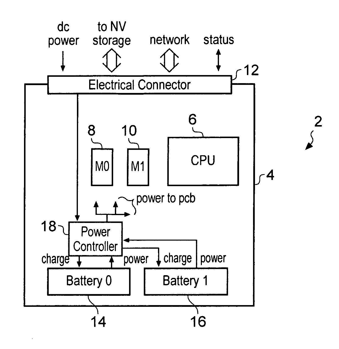
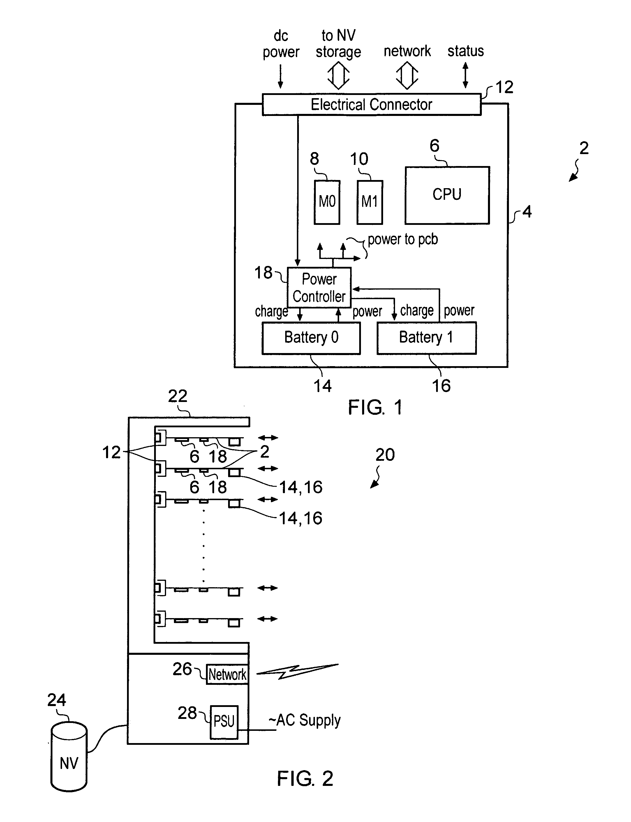
[0061]FIG. 1 illustrates a blade server 2 in the form of a printed circuit board 4 carrying a plurality of components, such as a processor 6 and on-board memory 8, 10 which together permit execution of a stream of program instructions. Some of the on-board memory 8, 10 may provide on-board non-volatile storage, e.g. a flash disk drive. It will be appreciated that many further on-board computing components are typically be provided such as, network interface units, memory controllers for communicating with non-volatile memory, such as hard disk drives located outside of the blade server 2, etc. An electrical connector 12 is provided at one edge of the blade server 2 and, in use, is connected to a blade enclosure. The electrical connector passes the main power supply (DC power) to the blade server 2 with this main power supply being used to power the blade server 2 when it is available. The electrical connector may additionally pass signals communicating with non-volatile storage (suc...


PUM


Abstract

A blade server 2 is provided with a processor 6 for executing program instructions and an electrical connector 12 for connecting to a blade enclosure 22. The blade server 2 also includes a power controller 18 connected to a plurality of power supply batteries 14, 16 which are provided on the blade server 2 itself. If the power controller 18 detects that the main power supply supplied via the electrical connector 12 has been interrupted, then a backup power supply to the processor is provided from the on-board power supply batteries 14, 16. The batteries 14, 16 on each blade are periodically discharged and recharged in turn to check their proper function.

Description

BACKGROUND OF THE INVENTION[0001]1. Field of the Invention[0002]This invention relates to the field of blade servers. More particularly, this invention relates to the provision of electrical power to blade servers.[0003]2. Description of the Prior Art[0004]It is known to provide blade servers and blade server arrays for use in high density computing applications. Typically blade servers comprise a bare circuit board (without an individual enclosure) to which is attached at least a processor for executing a stream of program instructions. The individual blade servers are connected via respective electrical connectors to a blade enclosure. A blade server array is provided by a blade enclosure housing a plurality of blade servers. Electrical power is supplied to the individual blade servers via the blade enclosure through the electrical connector. Such blade server arrays have a number of practical advantages in high performance applications, such as scaleability, redundancy, parallel ...

Claims


Application Information

Patent Timeline
Patent Type & Authority Applications(United States)
IPC IPC(8): G06F1/30
CPCG06F1/263G06F1/30
Inventor CHADIRCHI, IBRAHIM HIKMATHILL, STEPHEN JOHNSINTON, JOHN JULIANSAUNDERS, SPENCER JOHN
Owner ARM LTD
Learn More