Battery pack for driving electric motor of compact engine starting device, engine starting device driven by the battery pack, and manual working machine having the engine starting device

a technology for electric motors and starting devices, which is applied in the direction of machines/engines, propulsion parts, and flat cells. it can solve the problems of the inability of the engine to start with one pulling operation in many cases, and the complexity of the pulling operation itself. it achieves the effect of enhancing the durability reducing the size and weight of the starting device, and being small and ligh

Active Publication Date: 2009-04-28
HUSQVARNA ZENOAH
View PDF15 Cites 87 Cited by
  • Summary
  • Abstract
  • Description
  • Claims
  • Application Information

AI Technical Summary

Benefits of technology

[0036]In a preferred embodiment, the necessary discharge capacity is 1000 mAh. An output voltage of one cell is 3.8 V, if two cells are used, the voltage is 7.6 V, and even if the discharge current with respect to the electric motor for starting the engine is set to 10 to 60 A, this is sufficient capacity as a power supply for driving others. The lithium-based secondary battery of the invention which becomes a power supply of a compact engine starting device mounted on a working machine has sufficient capacity for starting the engine, its volume is extremely small, and even if the battery is incorporated in the starting device, the starting device can be compact incomparable with conventional technique.
[0045]If the engine of the working machine having the engine starting device of the above configuration and characteristics is provided, battery exhaustion is not caused, necessary discharge can always be carried out at the time of start of the engine, and the engine can smoothly start. When the lithium-based secondary battery employed in the invention is put on charge using the power generator, there is a tendency that the resistance in the battery is abruptly increased if the charging voltage exceeds 4.0 to 4.4 V, and the recovering ratio of the capacity is largely reduced. To prevent this, the battery pack is provided with a special overcharge preventing circuit, overcharge is prevented to increase the lifetime of the battery. If a rotation portion of the engine on which the magnet for the power generator is provided is a portion of a peripheral surface of a fan fixed to the crankshaft which always rotates together with the start of the engine, the power generation is started from the start of the engine, and it is only necessary to provide a coil, it is unnecessary to increase the conventional engine case itself in size. The effects which the present invention exerts are considerably great.

Problems solved by technology

Thus, if an operator has a weak strength or is an old person, or if the working space is small, the engine cannot be started with one pulling operation in many cases.
Hence, many proposals have been made to facilitate the start of an engine by pulling the recoil rope, and some of them become commercially practical, but complicated properties of the pulling operation itself still remain.
Thus, there is a limit for reducing the starting device in size and weight.
Therefore, the spiral spring barrel does not reversely rotate, but in a power transmitting mechanism using the meshing state between the worm gear and the worm wheel, the direction of the output shaft of the electric motor and the rotation driving shaft of the spiral spring barrel intersect with each other at right angles, the efficiency is poor (about 60%) and the device cannot be reduced in size in terms of design.
According to the engine starting device of the Japanese Utility Model Laid-Open Publication No. 63-110672, when the battery goes dead or the electric motor is broken, the engine starting device itself cannot be operated.
According to the Japanese Patent Laid-Open Publication No. 2002-285940, the spiral spring barrel is manually driven at the time of emergency by the recoil type drive mechanism, the entire apparatus corresponds to an apparatus in which the speed reducing mechanism is added to the conventional recoil type engine starting device as the electric motor, and since the speed reducing mechanism includes the worm and the worm wheel of the spiral spring barrel, the shaft of the electric motor and the support shaft of the spiral spring barrel is needed to intersect with each other at right angles, and it is difficult to reduce the entire apparatus in size.
Thus, it takes a long time until the spiral spring barrel is rotated to obtain a predetermined force in the spiral spring.
Thus, the entire apparatus becomes complicated, and its cost is naturally increased.
However, the ratchet wheel having the small diameter idles during the rotation of the engine.
Further, since the shafts of the electric motor, the spiral spring barrel, the ratchet wheel having the small diameter and the ratchet pawl are disposed in parallel to each other, this prevents the compact design of the engine starting device.
As described above, the mechanical problems of the compact engine starting devices discloses in Japanese Utility Model Laid-Open Publication No. 63-110672, Japanese Patent Laid-Open Publication No. 2002-285940, Japanese Patent Publication No. 2573340 and Japanese Utility Model Laid-Open Publication No. 2-13171 are solved by the Japanese Patent Application No. 2004-232139, but there still remains a problem concerning how the compact engine starting mechanism is smoothly, reliably and safely driven using the compact battery.
However, in order to start the engine ideally, several more batteries are required, but such batteries have too much volume to be accommodated in a switch box disposed at a steering wheel of the working machine, and naturally the batteries must be disposed in the starting device or other special location, and in order to reduce the batteries in size and weight, it exceeds a permissible range.

Method used


Image

  • Battery pack for driving electric motor of compact engine starting device, engine starting device driven by the battery pack, and manual working machine having the engine starting device
  • Battery pack for driving electric motor of compact engine starting device, engine starting device driven by the battery pack, and manual working machine having the engine starting device
  • Battery pack for driving electric motor of compact engine starting device, engine starting device driven by the battery pack, and manual working machine having the engine starting device

Examples


Embodiment Construction

[0063]A representative embodiment of the present invention will be explained concretely with reference to the accompanying drawings.

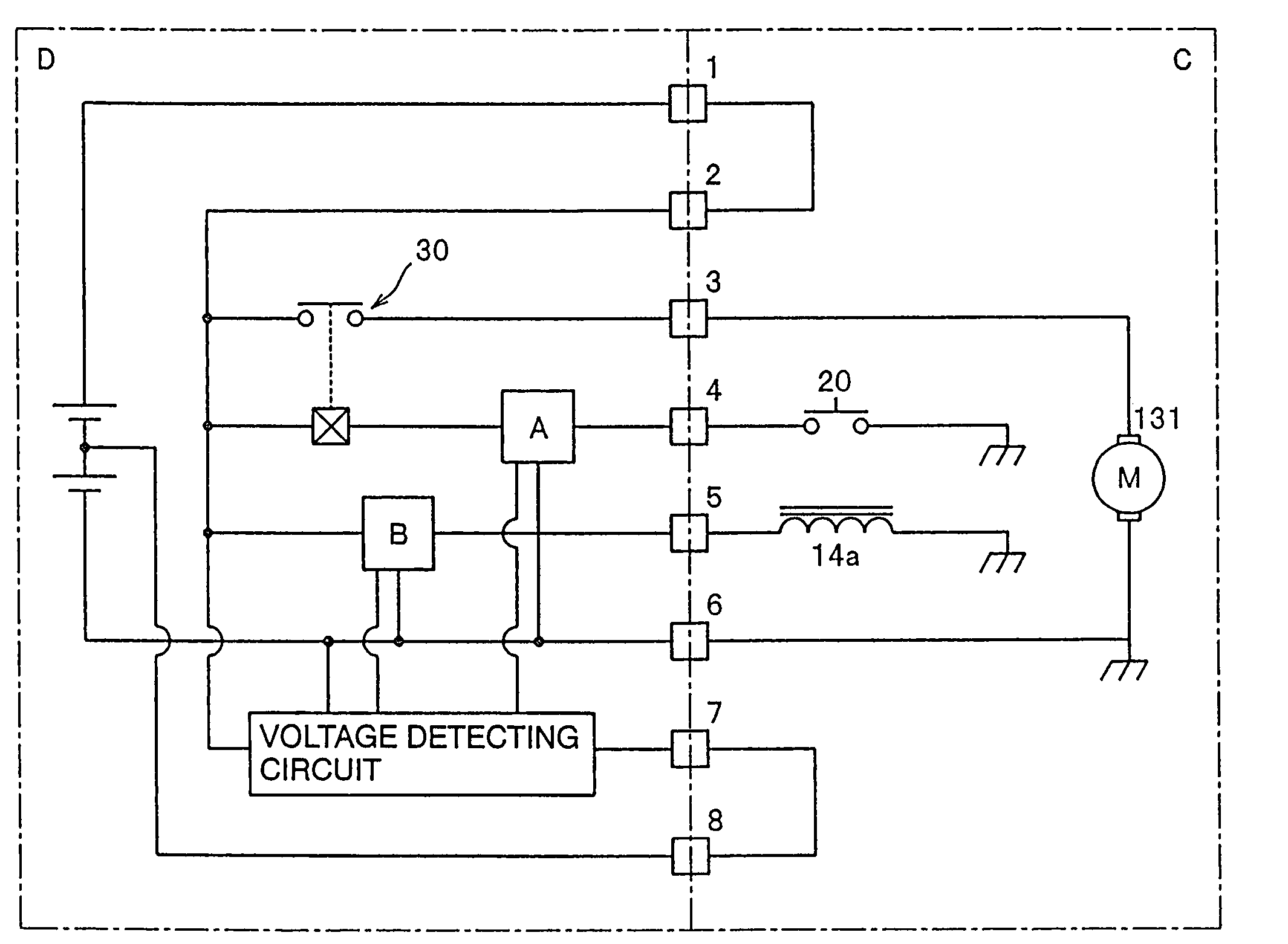
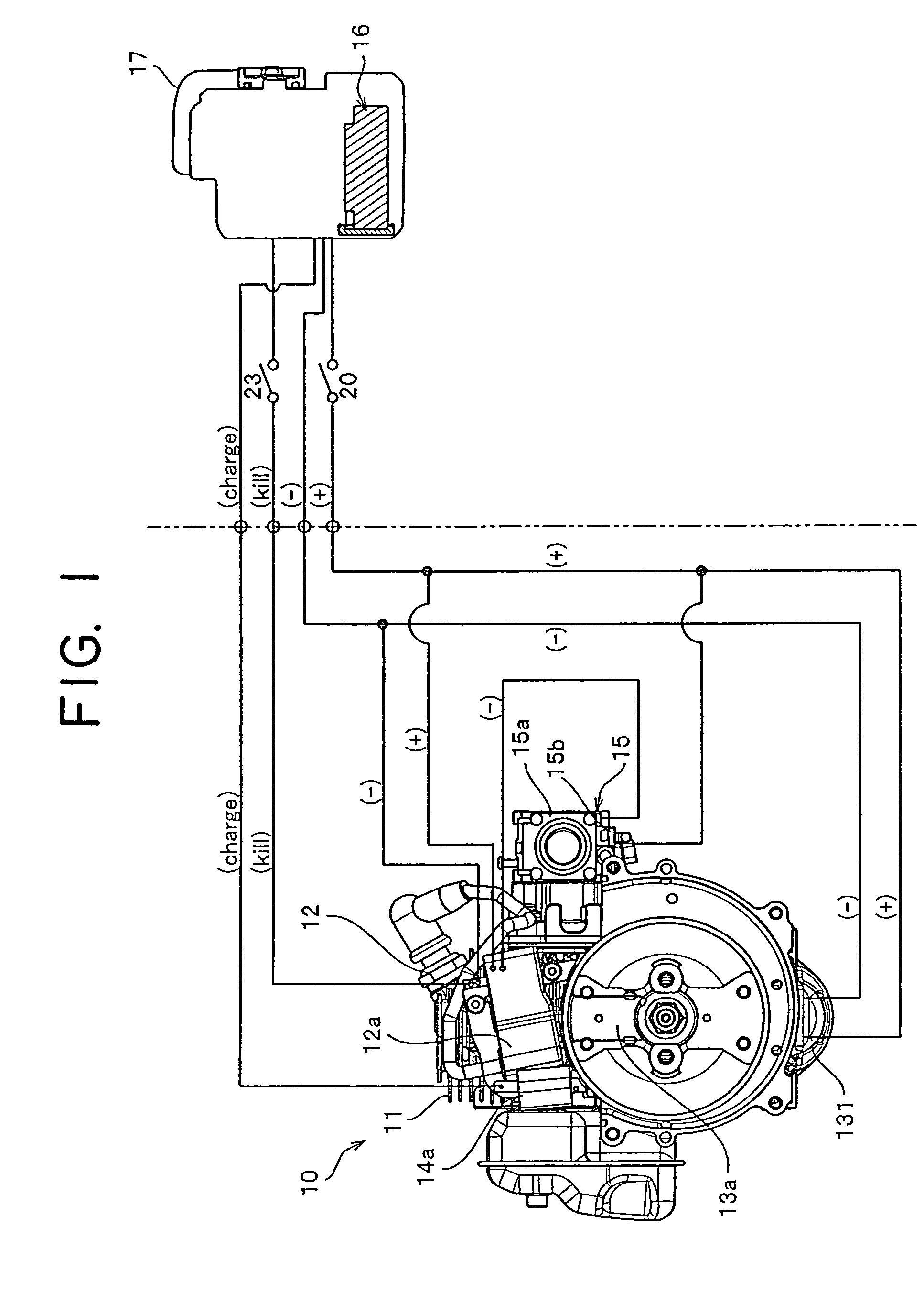
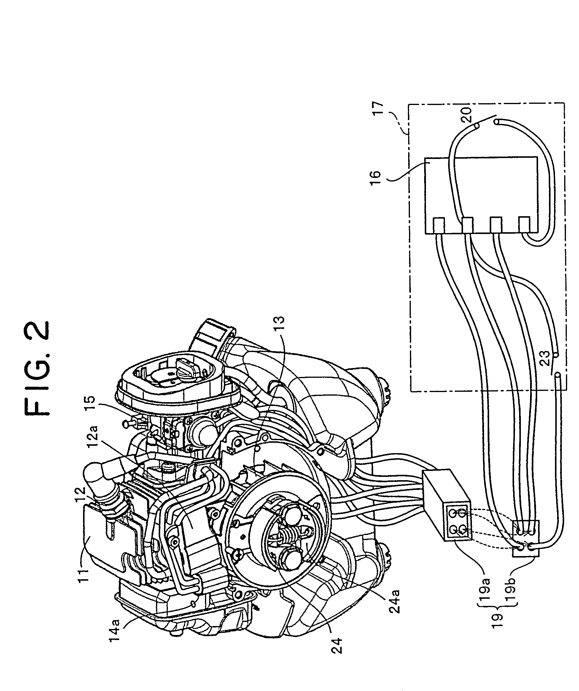
[0064]FIG. 1 is a diagram of a starting-circuit of a hybrid self-starter of a compact engine mounted in a working machine of the invention. FIG. 2 is a perspective view showing a concrete wiring between the compact engine and a battery accommodated in a switch box added to a steering wheel of the working machine.

[0065]Like the conventional engine shown in FIG. 2, the compact engine 10 of the embodiment includes a cylinder 11, a spark plug 12 facing a combustion chamber of the cylinder 11, a piston (not shown), a crankshaft (not shown), a fan 13 fixed to the crankshaft, and a centrifugal clutch (not shown) disposed on the back side (front side in FIG. 2) of the fan 13.

[0066]As shown in FIGS. 1 and 3, the compact engine 10 of the embodiment further includes, in addition to the above constituent members, a power generator 14 for charging a later-described ...


PUM

PropertyMeasurementUnit
charging voltageaaaaaaaaaa
discharge currentaaaaaaaaaa
timeaaaaaaaaaa

Abstract

This invention provides a battery pack for driving a compact electric motor of a compact engine starting device mounted on a working machine, comprising lithium-based secondary battery comprising two cells, the entire discharge capacity of the cells being 500 to 2000 mAh, charging voltage per one cell being 3.0 to 4.2 V, various electronic circuits like driving and battery protection circuits of an electric motor, maximum discharge current of the battery having high rate of 10 to 60 A, the protection circuit including an overdischarge inhibit circuit (A) interposed in the electric motor driving circuit and automatically stopping the driving operation of the electric motor after time required for starting the engine elapsed, the volume of the battery pack being as extremely low as 2.5×10⁴ to 1.0×105 mm3, the tire required until the engine is started from the actuation of the electric motor being set to an interval as short as 5 to 15 seconds, since high current can flow.

Description

BACKGROUND OF THE INVENTION[0001]1. Field of the Invention[0002]The present invention relates to a battery pack provided therein with a compact battery having large output which drives an ultra-compact electric motor for starting a compact engine mounted in a various working machine such as a carrying harvester, a chain saw, a lawnmower, a piggyback type harvester, a power spraying machine, an engine blower, a duster and a hedge trimmer, an engine starting device driven by a battery pack, and a manual working machine having the engine starting device.[0003]2. Description of the Related Art[0004]Currently, an engine starting device which starts a compact air-cooling type gasoline engine mounted in a manual working machine such as a widely used harvester and chain saw mostly includes a recoil type driving portion, a follower portion connected to a crankshaft of the engine through connecting / disconnecting means such as a centrifugal clutch, and a shock absorption•power accumulating por...

Claims


Application Information

Patent Timeline
Patent Type & Authority Patents(United States)
IPC IPC(8): H02J7/00B60K1/00F02N17/00H01M10/42H01M10/44H01M6/46F02N99/00H01M50/204H01M50/574
CPCH01M2/1072H01M2/34H01M10/42H01M10/425H01M10/052F02N11/08F02N2300/2011F02N11/0862Y02E60/10H01M50/204H01M50/574
Inventor MIYASHITA, SATOSHIONO, RYOUONIWA, TAKASHIHOKARI, HIROSHI
Owner HUSQVARNA ZENOAH
Why Eureka
Try Eureka