Air conditioner for vehicle with heat pump cycle

a technology for air conditioners and vehicles, applied in the direction of compression machines with several condensers, light and heating apparatus, transportation and packaging, etc., can solve the problems of difficult to achieve emission reduction, difficult to sufficiently clean exhaust gas, and inability to achieve the effect of reducing fuel consumption, preventing excessive heating capacity, and effective reducing fuel consumption

Inactive Publication Date: 2010-12-30
DENSO CORP
View PDF4 Cites 85 Cited by
  • Summary
  • Abstract
  • Description
  • Claims
  • Application Information

AI Technical Summary

Benefits of technology

[0035]According to another aspect of the present invention, an air conditioner for a vehicle includes: heating means for heating air to be blown into an interior of a vehicle compartment using a coolant of an internal combustion engine as a heat source; an electric heater for heating the air by being supplied with power; and control means for determining a target coolant temperature based on a target air temperature to be blown into the vehicle compartment. In the air conditioner, the control means decreases and corrects the target coolant temperature when the electric heater is operated. Thus, it can prevent heating capacity from being excessive, thereby effectively reducing fuel consumption.
[0036]According to another aspect of the present invention, an air conditioner for a vehicle includes: heating means for heating air to be blown into an interior of a vehicle compartment using a coolant of an internal combustion engine as a heat source; an electric heater for heating the air by being supplied with power; and control means for determining a target coolant temperature based on a target air temperature to be blown into the vehicle compartment, and for decreasing and correcting the target coolant temperature based on power consumption of the electric heater. In the air conditioner, the control means increases a correction amount for decreasing the target coolant temperature, as the power consumption of the electric heater becomes larger. Thus, it can prevent heating capacity from being excessive, thereby effectively reducing fuel consumption.
[0037]According to another aspect of the present invention, an air conditioner for a vehicle includes: heating means for heating air to be blown into an interior of a vehicle compartment by using a coolant of an internal combustion engine as a heat source; a seat heater disposed at a seat for generating heat by being supplied with power; and control means for determining a target coolant temperature based on a target air temperature to be blown into the vehicle compartment. In the air conditioner, the control means decreases and corrects the target coolant temperature when the seat heater is operated. Thus, when the seat heater is operated, the warm feeling given to the passenger can be improved while the fuel consumption can be improved.
[0038]According to another aspect of the present invention, an air conditioner for a vehicle includes: heating means for heating air to be blown into an interior of a vehicle compartment using a coolant of an internal combustion engine as a heat source; a seat heater disposed at a seat for generating heat by being supplied with power; and control means for determining a target coolant temperature based on a target air temperature to be blown into the vehicle compartment, and for decreasing and correcting the target coolant temperature based on power consumption of the seat heater. In the air conditioner, as the power consumption of the seat heater becomes larger, the control means increases a correction amount for decreasing the target coolant temperature. Thus, when the seat heater is operated, it can prevent warm feeling of a passenger from being excessive, while the fuel consumption can be improved.

Problems solved by technology

The technique disclosed in JP-A-10-100652, however, has various problems in practical use.
For example, the heater system using the combustion heater makes it difficult to sufficiently clean exhaust gas from the combustion heater, and thus cannot achieve reduction in emission.
That is, provision of an exhaust emission control system or the like dedicated to the combustion heater is proposed for sufficiently cleaning the exhaust gas from the combustion heater, but is difficult to perform within the limited cost and space for mounting.
For example, the heater system using the PTC heater is difficult to ensure adequate heating capacity within the constraints of cost and mounting space.
In a vehicle for achieving fuel consumption saving by stopping an engine, for example, in a hybrid car, an engine coolant is often at a low temperature, and thus the use of the engine coolant as a heat source for heating cannot ensure adequate heating capacity.

Method used


Image

  • Air conditioner for vehicle with heat pump cycle
  • Air conditioner for vehicle with heat pump cycle
  • Air conditioner for vehicle with heat pump cycle

Examples


first embodiment

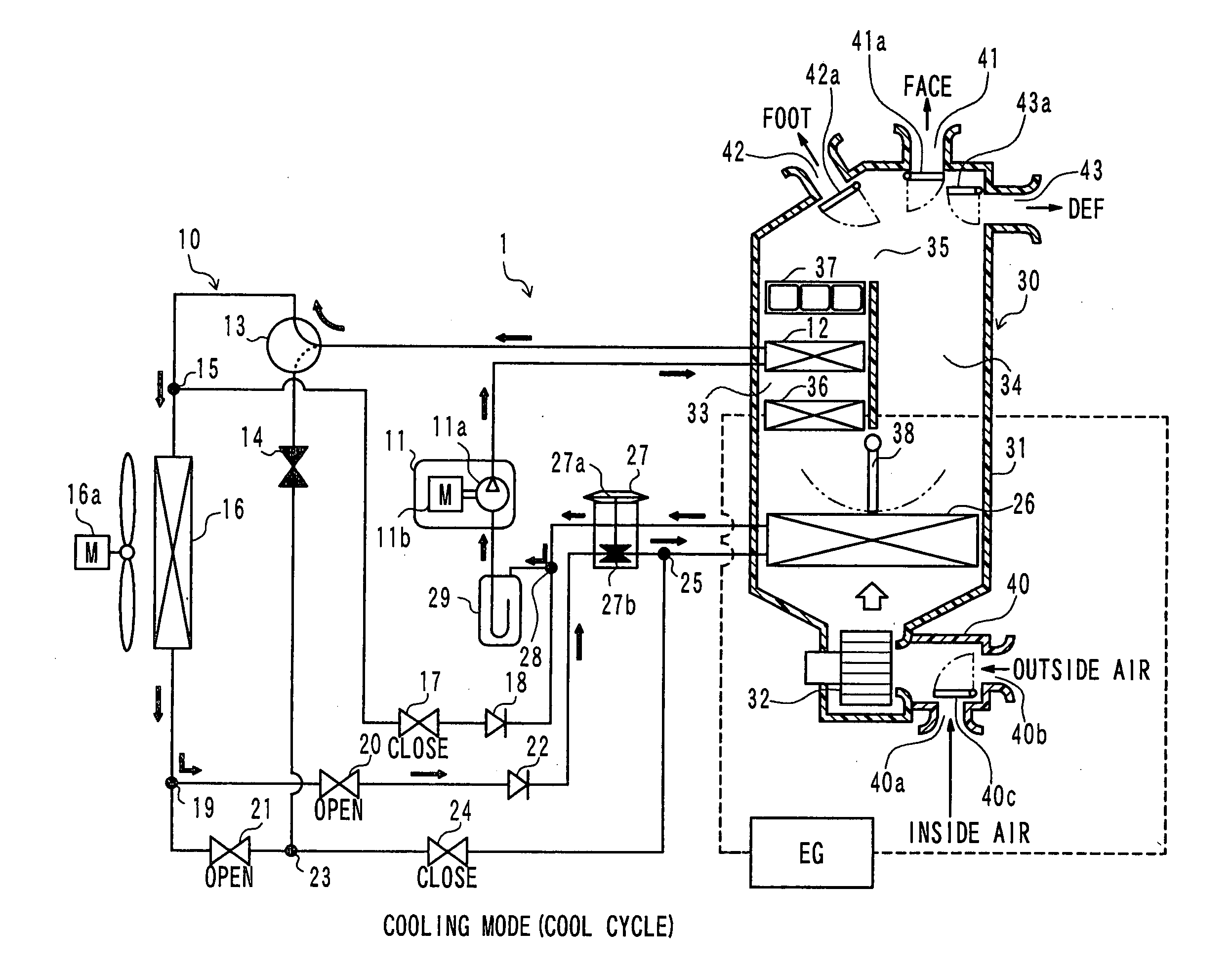
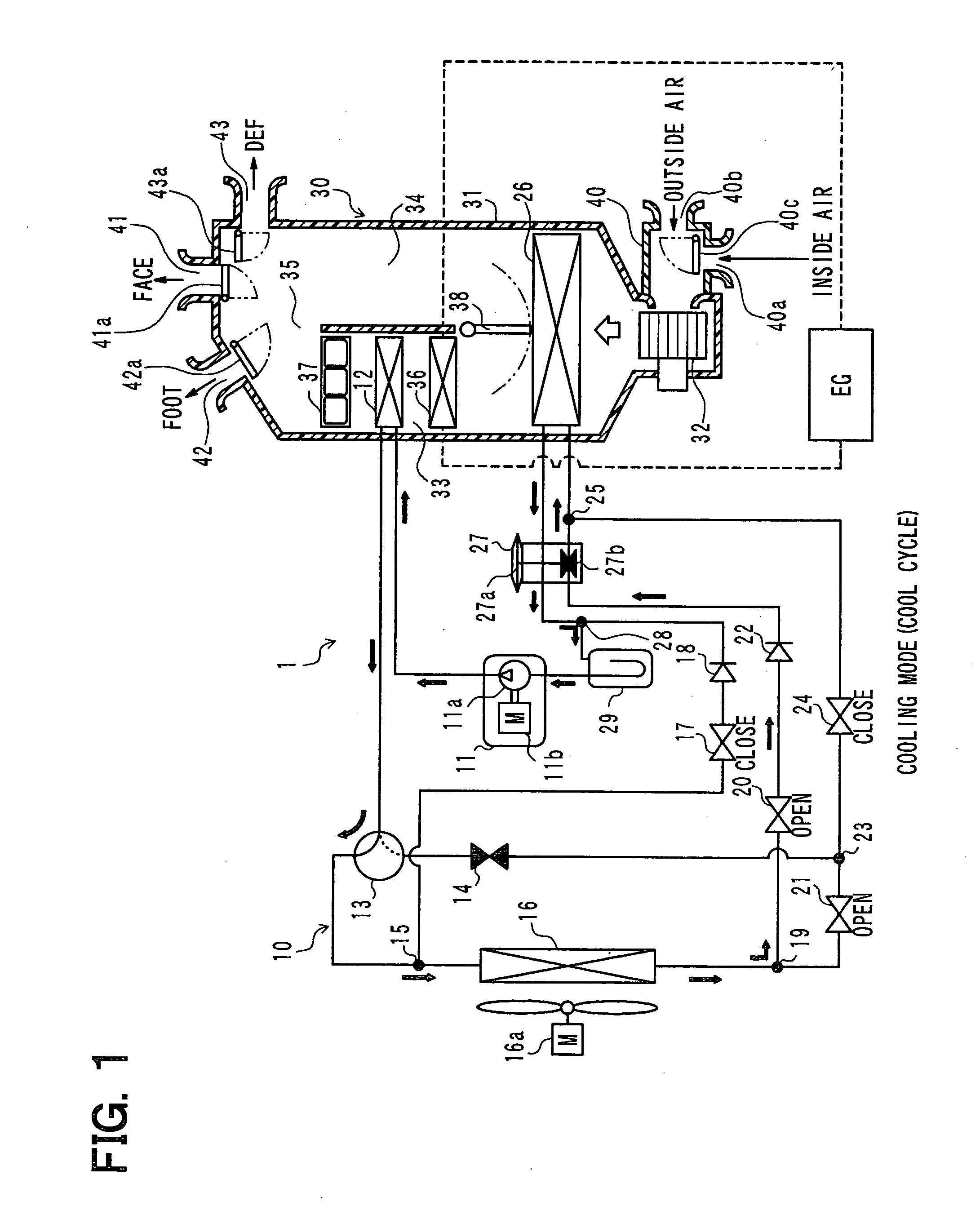
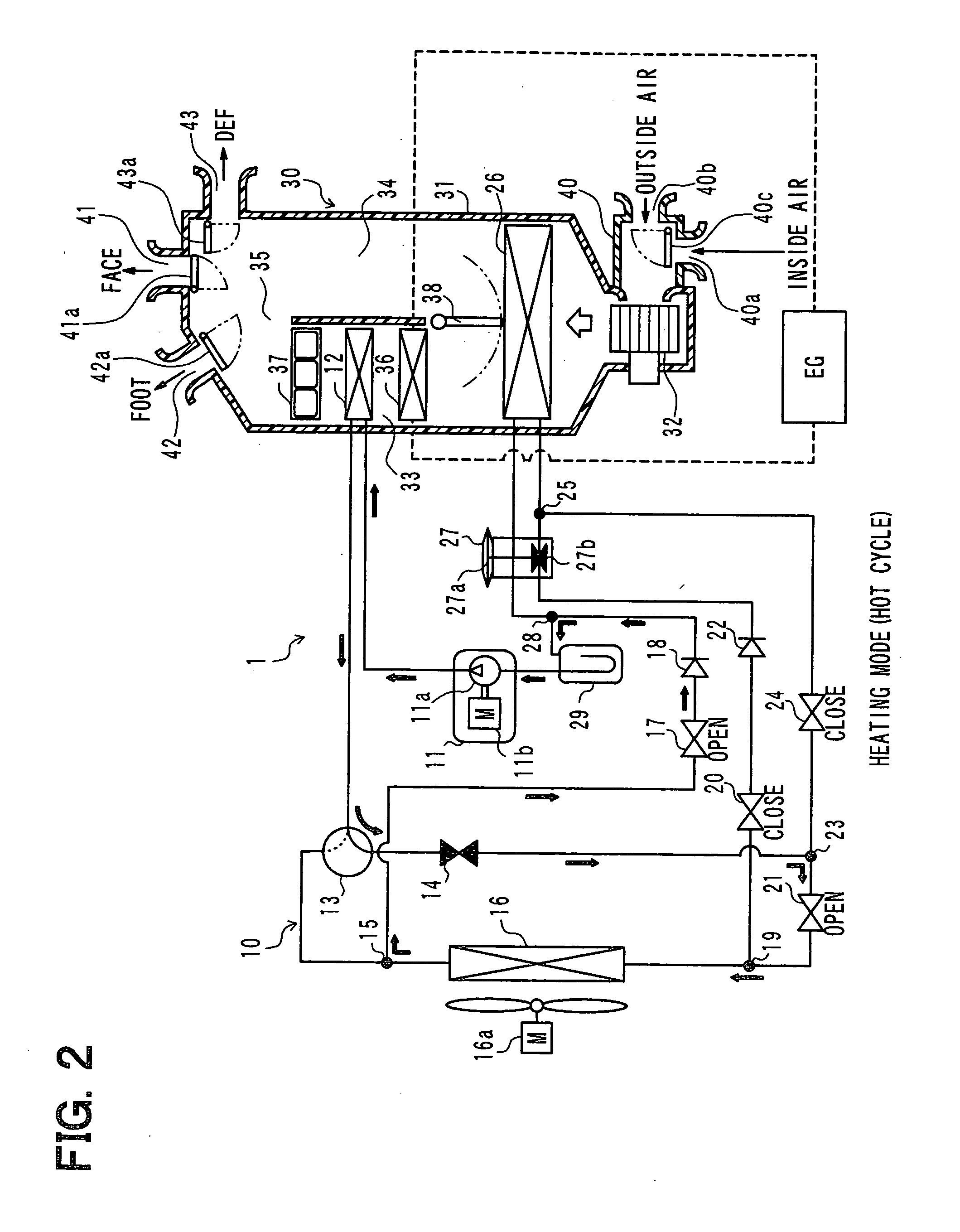
[0058]A first embodiment of the invention will be described below with reference to FIGS. 1 to 9. In the present embodiment, an air conditioner for a vehicle of the invention is applied to the so-called hybrid car which obtains a driving force for a vehicle traveling from an internal combustion engine (engine) EG and an electric motor for traveling. FIGS. 1 to 4 show an entire configuration diagram of an air conditioner 1 for a vehicle, according to the first embodiment and the following embodiments described later.

[0059]The air conditioner for a vehicle includes a vapor compression refrigeration cycle 10 which can switch among refrigerant circuits in a cooling mode (COOL cycle) for cooling the vehicle interior, in a heating mode (HOT cycle) for heating the vehicle interior, and in a first dehumidification mode (DRY_EVA cycle) and in a second dehumidification mode (DRY_ALL cycle) for dehumidifying the vehicle interior. FIGS. 1 to 4 indicate the flows of refrigerant in the cooling mo...

second embodiment

[0223]In the above first embodiment, heating using the heater core 36 (i.e., heating using the engine coolant as a heat source) is selected at the extreme-low outside air temperature lower than −5° C. In contrast, in a second embodiment, as shown in FIG. 10, heating by the heater core 36 (i.e., heating using the engine coolant as a heat source) is selected when the vehicle interior preset temperature Tset is set to a very high temperature higher than 31° C.

[0224]That is, when the heat pump cycle is selected while the vehicle interior preset temperature Tset is set to a very high temperature, the operating rate of the heat pump cycle becomes high, thereby rapidly causing the frost formation on the outdoor heat exchanger 16. The frost formation on the outdoor heat exchanger 16 reduces the heat exchange efficiency of the outdoor heat exchanger 16, degrading the heating capacity.

[0225]In the present embodiment, when the vehicle interior preset temperature Tset is set to a very high temp...

third embodiment

[0236]In the above first embodiment, the heating using the heater core 36 (i.e., heating using the engine coolant as a heat source), and the dehumidification using the cooler cycle are performed at the extreme-low outside air temperature lower than −5° C. However, in a third embodiment, as shown in FIG. 11, heating is performed using both of the heater core 36 (i.e., heating using the engine coolant as a heat source) and the heat pump cycle at a low outside air temperature lower than −2° C.

[0237]Now, the process in step S6 of the present embodiment will be described in detail below. FIG. 11 is a flowchart showing a main part of the process in step S6. The control process shown in the flowchart of FIG. 11 is carried out when the air conditioner switch 60a and the automatic switch 60b are turned on (ON), or the like.

[0238]In step S70, it is determined whether the present air conditioning control is pre-air conditioning or not. When the present air conditioning control is determined no...


PUM


Abstract

An air conditioner for a vehicle includes a vapor compression refrigeration cycle configured to have a heat pump cycle for heating air to be blown into an interior of a vehicle compartment, and a heating member for heating the air using a coolant of an internal combustion engine of the vehicle as a heat source. In the air conditioner, an operation request signal is output by an air conditioning controller to the internal combustion engine when an outside air temperature is lower than a predetermined threshold.

Description

CROSS REFERENCE TO RELATED APPLICATION[0001]This application is based on Japanese Patent Application No. 2009-152095 filed on Jun. 26, 2009, the contents of which are incorporated herein by reference in its entirety.FIELD OF THE INVENTION[0002]The present invention relates to an air conditioner for a vehicle, which is provided with a heat pump cycle.BACKGROUND OF THE INVENTION[0003]Conventionally, JP-A-10-100652 discloses regarding an air conditioner for a vehicle, which includes a heat-pump heating system for performing a heating operation by use of a heat pump, and a heater system for performing a heating operation by using hot water or heat from a heating element.[0004]JP-A-10-100652 takes into consideration the fact that a heating efficiency of the heat-pump heating system becomes deteriorated under an atmosphere where the temperature of outside air is extremely low. Thus, at the extremely-low outside air temperature, the heating is performed by the heater system, while stopping...

Claims


Application Information

Patent Timeline
Patent Type & Authority Applications(United States)
IPC IPC(8): F25B1/00
CPCB60H1/00785B60H1/00921B60H1/3208B60H2001/00128F25B47/02B60H2001/3292F25B6/04F25B41/04B60H2001/3273F25B41/20F25B41/24
Inventor OOMURA, MITSUYOHAYASHI, HIROYUKITANIHATA, TAKUYAICHISHI, YOSHINORI
Owner DENSO CORP
Why Eureka
Try Eureka