Jar or Tin Lid

a lid and tin technology, applied in the field of lids, can solve the problems of high power force, inability to apply the required force for opening the lid and overcoming the vacuum force, and inability to solve the solution available to open the screw-lock mechanism of containers with tight lids altogether. , to achieve the effect of increasing stability

Inactive Publication Date: 2008-08-28
ANTON DUSEL +3
View PDF13 Cites 5 Cited by
  • Summary
  • Abstract
  • Description
  • Claims
  • Application Information

AI Technical Summary

Benefits of technology

[0012]The plate or disk between the top edge of the jar and the inner side of the lid consists of metal, plastics, rubber or the like material, and will be applied to the top edge of the jar when being closed, whereby a sealing ring is arranged on the edge of the plate, which is in sealing engagement with the peripheral edge of the jar. The opening in the plate is closed by means of the seal fastened on the inner side of the lid as soon as the vacuum in the jar has been generated so that the vacuum in the jar is maintained, when the lid is applied to the jar. Sealing means between the lid and the plate, which are used for closing the opening in the plate, for example is a seal in disk or ring form, which prevents that vacuum in the jar above the aperture is removed and air from the surroundings is able to flow through the gap between the jar and the lid into the jar. For this purpose the plate is also sealed against the peripheral edge of the jar, whereby the sealing effect is generated at the outer restriction of the plate, which is in engagement with the peripheral edge of the jar if the plate does not operate itself as the seal.
[0013]This allows that the sealing surface which is required for closing the opening in the plate, is under relatively small pressure in view of the vacuum existing within the jar, compared with the large peripheral area of known comparable closures so that besides of the screw closure between the lid and the jar only that limited atmospheric pressure, which acts upon the sealing is to be overcome when opening the glass, and in this manner with the existing low pressure within the jar can be easily opened.
[0014]According to a second aspect of the invention the disk-like plate is formed as an uninterrupted surface, which means is without any aperture, whereby the peripheral rim together with the disk-like plate is in tight contact across the entire periphery with the plate if the jar or the tin is closed so that the vacuum within the jar or the tin is maintained. The effect of an opening in the plate, which is obtained by sealing means between the lid and the plate, is obtained with this type of structure in a corresponding manner by the fact that when rotating the lid relative to the jar or to the tin the lid in view of the thread pitch undergoes a movement in height relative to the jar or the tin, and with this type of rotation of the lid the sealing between the plate and the peripheral edge of the jar will be compensated or interrupted so that in this manner air can flow from the outside inwardly, and in this way opening the jar will be possible without any considerable effort.
[0016]According to a further embodiment of this invention the lid and / or the plate or alternatively the disk are provided with a downwardly or upwardly extending deformation formed as a depression, which is arranged concentrically around the opening within the plate. Between the lid and the plate a rubber seal formed as a sealing disk or a sealing ring is provided. This arrangement allows that by means of a trough a centring effect is obtained when the lid is seated, that the trough within the lid can be used as a recess for inserting labels or the like, that the seal between the lid and the plate undergoes a slight pretension when both are closed, and that by means of the deformation lid and plate obtain an increased stability. Alternately, the trough within the lid can be formed when the plate is provided without any trough so that the seal arranged between both and the lid in it's closed condition has a firm seat based on it's compression.

Problems solved by technology

Jars with a screw-lock or a twist-lock mechanism, especially with a relatively large diameter of the lid, such as for jars including fruit, vegetables or the like, which are to be kept shut in an airtight manner, in view of quality and safety reasons in general are stored under high vacuum, and therefore require high power force if they are to be opened for the first time.
The proposals for solutions available in order to open such screw-lock mechanisms of containers with tight lids altogether are not satisfactory, especially there are many users, who are not able to apply the required forces for opening the lid and for overcoming the vacuum forces.

Method used


Image

  • Jar or Tin Lid
  • Jar or Tin Lid
  • Jar or Tin Lid

Examples


Embodiment Construction

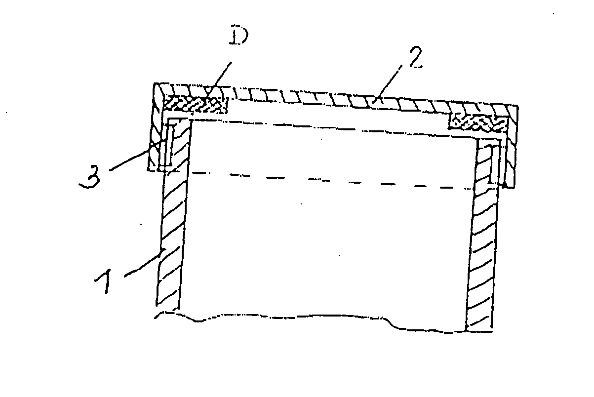
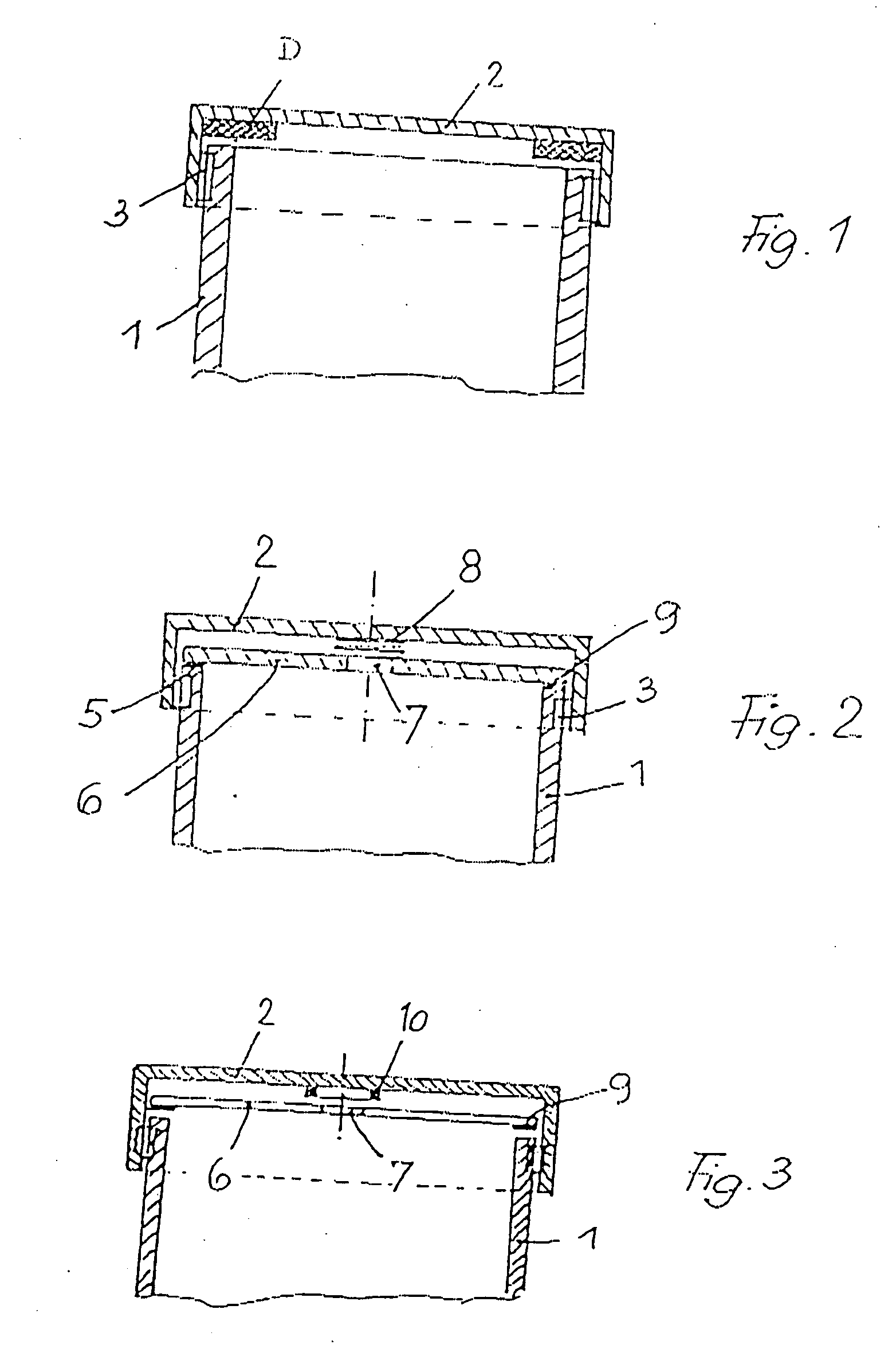
[0024]With a conventional embodiment of a jar 1 closed by a lid, in which food products are conserved by vacuum, a lid 2 is attached to the top side of the jar. The lid is screwed onto the top of the jar 1 at 3 and is locked by means of a screwing or twisting-off-closure. On the inner side of the lid a seal 4 is arranged at the peripheral edge of the bottom of the lid, which seal is in engagement with the top edge of the jar so that within the jar underpressure will be maintained for conserving the content. The seal 4 is a sealing ring firmly connected with the inner side of the lid. The diameter of the sealing ring corresponds with the inner diameter of the lid.

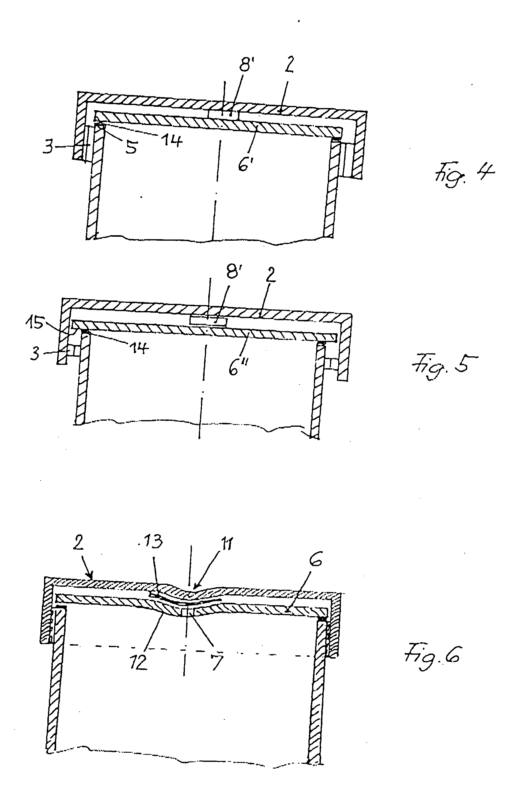
[0025]The arrangement according to FIG. 2, which is an embodiment of the lid system according to the invention, shows a plate 6 resting upon the top peripheral edge 5 of jar 1, which plate has a central opening 7 in engagement with a seal 8 firmly connected to the inner side of the lid, and shuts the opening 7 so that the lo...


PUM


Abstract

The invention relates to a lid for jars or tins having a screw-lock or twist-lock mechanism for sealing the content of the jar or tin in an air-tight manner. The lid is made up of a rubber or plastic seal between the inside of the lid and the upper peripheral edge of the jar or tin. The lid has a discoid plate having a continuous opening or alternatively-no opening is inserted between the lid and the upper edge of the jar or tin. The peripheral edge representing the upper edge of the jar or tin is configured to form a tight seal with the discoid plate when the jar or tin is closed. The opening of the plate is associated with a seal facing the inside of the lid and blocking air from penetrating the opening.

Description

BACKGROUND OF THE INVENTION[0001]This invention refers to a lid for a jar or a tin with a screw-lock or twist-lock mechanism for sealing the content of the glass jar or tin in an air-tight manner. The lid comprises an annular sealing ring of rubber or plastics material between the inner side of the lid and the upper peripheral edge of the jar or tin, whereby a disk-like plate with a continuous opening is provided between the lid and the upper edge of the jar or the tin. This opening is provided with a seal, which closes the opening at the inner side of the lid.[0002]Jars with a screw-lock or a twist-lock mechanism, especially with a relatively large diameter of the lid, such as for jars including fruit, vegetables or the like, which are to be kept shut in an airtight manner, in view of quality and safety reasons in general are stored under high vacuum, and therefore require high power force if they are to be opened for the first time. In overcoming this high vacuum pressure auxiliar...

Claims


Application Information

Patent Timeline
Patent Type & Authority Applications(United States)
IPC IPC(8): B65D41/08B65D53/00B65D51/16B65D51/18
CPCB65D51/1672B65D51/1688B65D2543/00972B65D2251/0018B65D2251/0081B65D51/18
Inventor DUSEL, ANTON
Owner ANTON DUSEL
Why Eureka
Try Eureka