Method and system for fuel system control

a fuel system and control system technology, applied in the direction of electric control, combustion air/fuel air treatment, machines/engines, etc., can solve the problems of tailpipe emissions, overall drivability, tailpipe emissions, tailpipe emissions, etc., to reduce fuel emissions, reduce engine operation times, and fuel economy

Active Publication Date: 2015-05-12
FORD GLOBAL TECH LLC
View PDF15 Cites 2 Cited by
  • Summary
  • Abstract
  • Description
  • Claims
  • Application Information

AI Technical Summary

Benefits of technology

[0002]Reduced engine operation times in hybrid vehicles enable fuel economy and reduced fuel emissions benefits. However, the shorter engine operation times can lead to insufficient purging of fuel vapors from the vehicle's emission control system as well as insufficient time for completion of a fuel system leak diagnostics operation. To address some of these issues, hybrid vehicles may include a vapor blocking valve (VBV) between a fuel tank and a hydrocarbon canister of the emission system to limit the amount of fuel vapors absorbed in the canister. An opening or closing of the VBV may then be adjusted based on fuel system conditions to enable fuel vapor purging or leak diagnostics.
[0004]However, the inventors herein have identified potential issues with such systems. As one example, during purging operations, to promote drawing of hydrocarbons from the canister to the engine intake, while also reducing the amount of fuel tank vapors that are drawn into the engine intake, the VBV has to be powered closed and / or a negative pressure has to be maintained in the fuel tank. In particular, each time the engine is turned off (e.g., to operate the vehicle in a battery mode, or for an engine idle-stop), or when purge is periodically turned off during an engine running event, the VBV has to be powered open to allow the fuel tank to vent pressure developed from vapor generation in the tank into the purge canister. Before purge operations can be subsequently resumed, the VBV is powered closed to isolate the fuel tank, forcing fresh air to flow through the canister bed and increasing canister purge. As such, if the VBV were not closed, the purge flow would draw hydrocarbons out of the fuel tank vapor dome through a buffer area of the canister (thereby bypassing the canister carbon bed) until the fuel tank was at a negative pressure where the path of least resistance would be to come via the carbon bed. Due to the shorter purge times available in hybrid vehicles, purge operations tend to be more aggressive with higher purge ramp rates (relative to corresponding non-hybrid vehicles). Drawing vapors directly from the fuel tank during such aggressive purges can cause substantial air / fuel ratio excursions which in turn degrade combustion stability, tailpipe emissions and overall drivability. In some embodiments, the fuel tank pressure may need to be pumped down to negative pressure levels at each purge cycle to enable purging through the canister bed. As such, these additional steps greatly reduce the already limited time available for purging in hybrid vehicles.
[0005]In one example, some of the above issues may be at least partly addressed by a method for a fuel system in a hybrid vehicle, comprising purging hydrocarbons from a canister to an engine intake with a vent valve and a purge valve open, and during the purging, selectively closing the vent valve while the purge valve remains open responsive to a fuel tank pressure to maintain vacuum in the fuel tank. In this way, dependence on a vapor blocking valve for managing fuel tank pressures can be reduced.
[0006]As an example, a fuel system in a hybrid vehicle may include a fuel tank coupled to an engine intake via a canister and each of a canister vent valve and a canister purge valve. During purging conditions, such as when a canister load is higher than a first threshold, an engine controller may open a purge valve to apply an engine intake vacuum on the canister carbon bed and draw out the stored hydrocarbons. Following opening the purge valve, the vent valve may also be opened to allow fresh air to flow over the canister bed. The vent valve may be kept open until a desired amount of fuel system vacuum (e.g., fuel tank vacuum) is generated. Specifically, the vent valve may be selectively closed during the purging responsive to the fuel tank pressure to generate and hold a fuel tank vacuum. Then, when the canister purging has been completed, the purge valve may be closed. While the vent valve is closed, the fuel tank vacuum can be monitored for fuel system leaks. During a subsequent purging operation, the purge valve may be opened before the vent valve is opened so that purging is initiated under fuel tank negative pressure conditions. The negative fuel tank pressure causes the path of least resistance for the applied vacuum to be via the canister bed, improving purging of canister hydrocarbons and reducing drawing of fuel tank vapors into the engine intake.
[0007]In this way, by timing the closing of a vent valve during canister purging based on a fuel tank pressure, a fuel tank and a vapor path leading fuel tank vapors to an engine intake may be sealed without necessitating a vapor blocking valve. By coordinating closing of the vent valve with closing of the purge valve, at least some negative pressure can be maintained in the fuel system, enhancing drawing of hydrocarbons from the canister into the intake and reducing drawing of fuel tank vapors directly into the engine intake. In this way, air / fuel ratio excursions caused by fuel tank vapors entering the intake can be reduced. In addition, purge delays incurred due to tank pressure bleed down and vapor blocking valve operations can be reduced. By performing leak detection routines while the vent valve is closed, the vacuum held in the fuel system can be advantageously used to complete fuel system diagnostics. By improving the completion frequency of both purging and leak detection operations, emissions compliance may be better ensured.

Problems solved by technology

However, the shorter engine operation times can lead to insufficient purging of fuel vapors from the vehicle's emission control system as well as insufficient time for completion of a fuel system leak diagnostics operation.
However, the inventors herein have identified potential issues with such systems.
Drawing vapors directly from the fuel tank during such aggressive purges can cause substantial air / fuel ratio excursions which in turn degrade combustion stability, tailpipe emissions and overall drivability.

Method used


Image

  • Method and system for fuel system control
  • Method and system for fuel system control
  • Method and system for fuel system control

Examples


Embodiment Construction

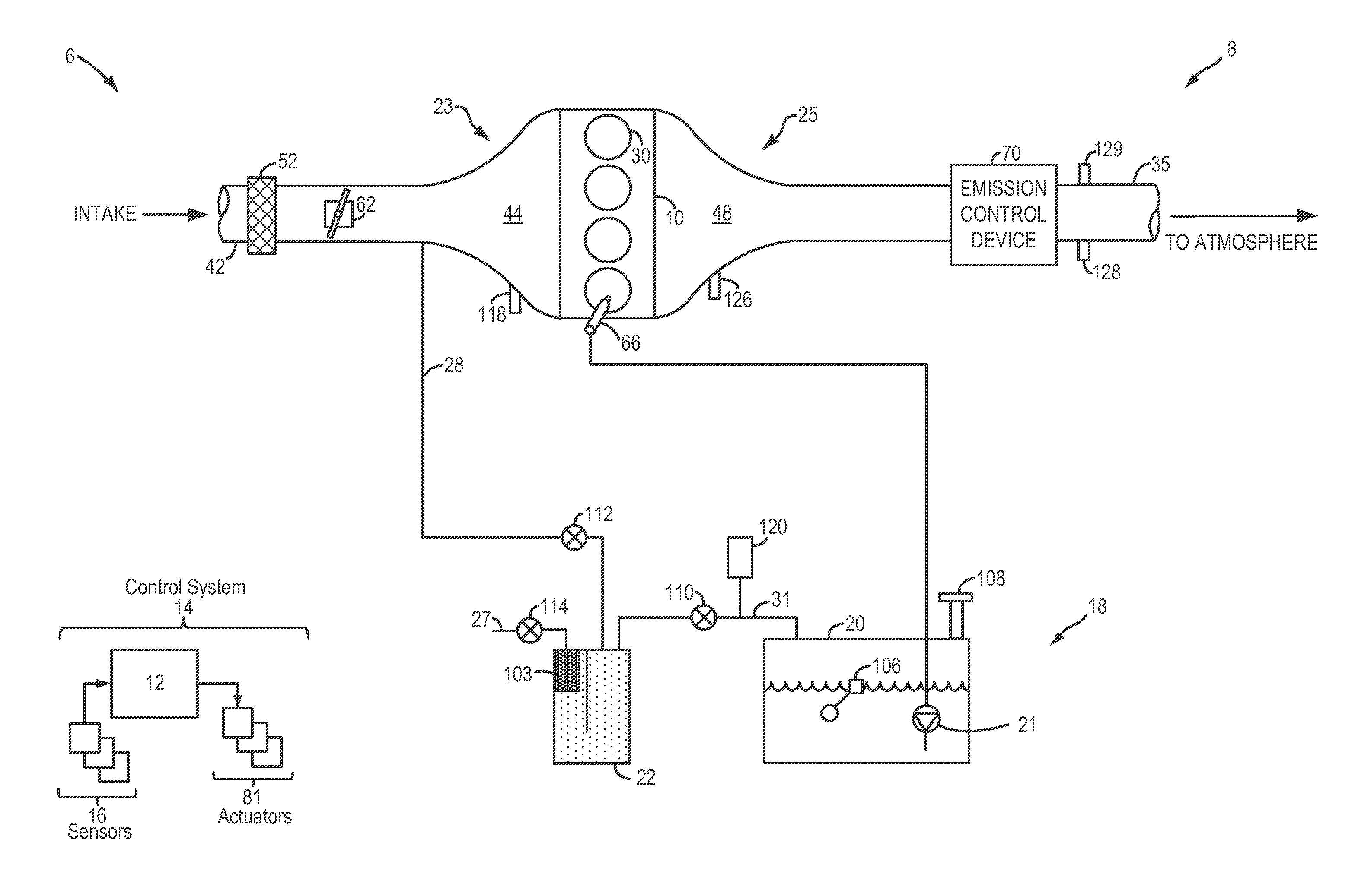
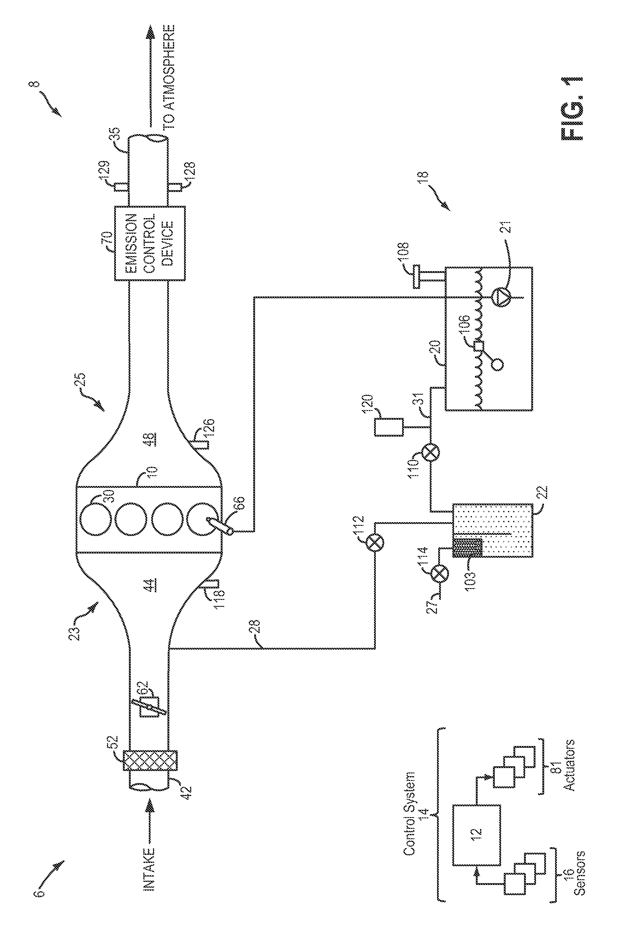
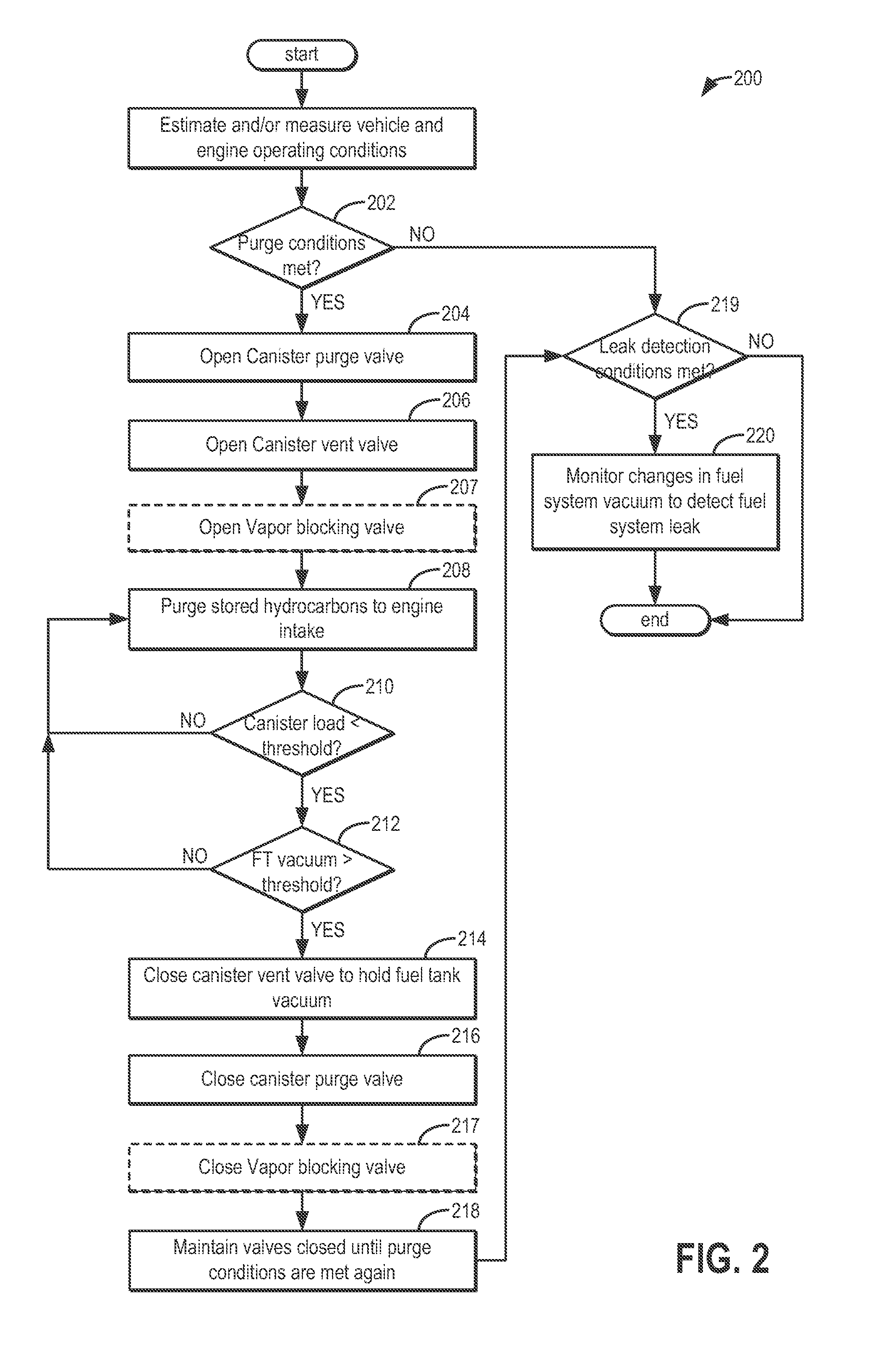
[0012]Methods and systems are provided for generating and maintaining at least some negative pressure in a fuel system coupled to a hybrid vehicle, such as the fuel system of FIG. 1. A controller may be configured to perform a control routine, such as the example routine of FIG. 2, to coordinate the closing of a canister vent valve before the closing of a canister purge valve when a purging operation is stopped to hold at least some vacuum in the fuel tank. Then, during a subsequent canister purge, the purge valve can be opened before opening the vent valve, allowing purge to initiate under fuel tank vacuum conditions. The controller may also perform leak detection tests during non-purging conditions while vacuum is held in the fuel system. An example fuel system operation is described at FIG. 3. In this way, purging and leak detection can be better completed during the limited purge time available in hybrid vehicles.

[0013]FIG. 1 shows a schematic depiction of a hybrid vehicle syste...


PUM


Abstract

Methods and systems are provided for controlling a fuel system in a hybrid vehicle. Before canister purging is stopped by closing a purge valve, a canister vent valve is closed to hold fuel tank vacuum. Then, during a subsequent canister purge, the purge valve is opened before opening the vent valve, allowing canister purge to initiate under fuel tank vacuum conditions.

Description

FIELD[0001]The present description relates to systems and methods for maintaining vacuum in the fuel system of a hybrid vehicle.BACKGROUND AND SUMMARY[0002]Reduced engine operation times in hybrid vehicles enable fuel economy and reduced fuel emissions benefits. However, the shorter engine operation times can lead to insufficient purging of fuel vapors from the vehicle's emission control system as well as insufficient time for completion of a fuel system leak diagnostics operation. To address some of these issues, hybrid vehicles may include a vapor blocking valve (VBV) between a fuel tank and a hydrocarbon canister of the emission system to limit the amount of fuel vapors absorbed in the canister. An opening or closing of the VBV may then be adjusted based on fuel system conditions to enable fuel vapor purging or leak diagnostics.[0003]One example approach for fuel system control is shown by Rockwell et al. in U.S. Pat. No. 7,594,500. Therein, the fuel tank is coupled to a canister...

Claims


Application Information

Patent Timeline
Patent Type & Authority Patents(United States)
IPC IPC(8): F02D41/00F02M33/02B60W20/00B60K15/01F02M25/08B60K15/035
CPCB60K15/035B60K15/01Y10T137/0396F02D41/0032B60W20/00F02D41/0035F02M25/0836F02D41/004B60Y2200/92F02M33/02
Inventor PIFHER, KENNETH L.PETERS, MARK W.
Owner FORD GLOBAL TECH LLC
Why Eureka
Try Eureka