
MRI apparatus

a magnetic resonance imaging and apparatus technology, applied in the direction of instruments, patient positioning for diagnostics, using reradiation, etc., can solve the problems of uneasiness that may be applied to the person, insufficient, insufficient to provide the person with a comfortable occupant, etc., to improve the sense of safety and comfort that the person feels

Active Publication Date: 2008-08-28
TOSHIBA MEDICAL SYST CORP
View PDF20 Cites 27 Cited by
  • Summary
  • Abstract
  • Description
  • Claims
  • Application Information

AI Technical Summary

Benefits of technology

[0007]The present invention has taken into consideration the above-described problems, and it is an object of the present invention to provide the MRI apparatus which can improve a sense of safety and a comfort that the person feels.

Problems solved by technology

Since an opening (space) formed to a gantry of the MRI apparatus, through which the person is inserted, has only a size that permits the person to enter thereinto, there is a possibility that a feeling of uneasiness may be applied to the person who is subjected to an examination from that time.
JP-A 2006-110043”, cannot sufficiently eliminate the feeling of uneasiness of the person before the person is inserted into the opening as well as cannot sufficiently provide the person with a comfortable occupant feeling when the person is inserted into the opening, although the lighting unit can light the opening and the gantry brightly.

Method used


Image

  • MRI apparatus
  • MRI apparatus
  • MRI apparatus

Examples


Embodiment Construction

[0024]An embodiment of an MRI apparatus according to the present invention will be explained below referring to FIG. 1 to FIG. 11.

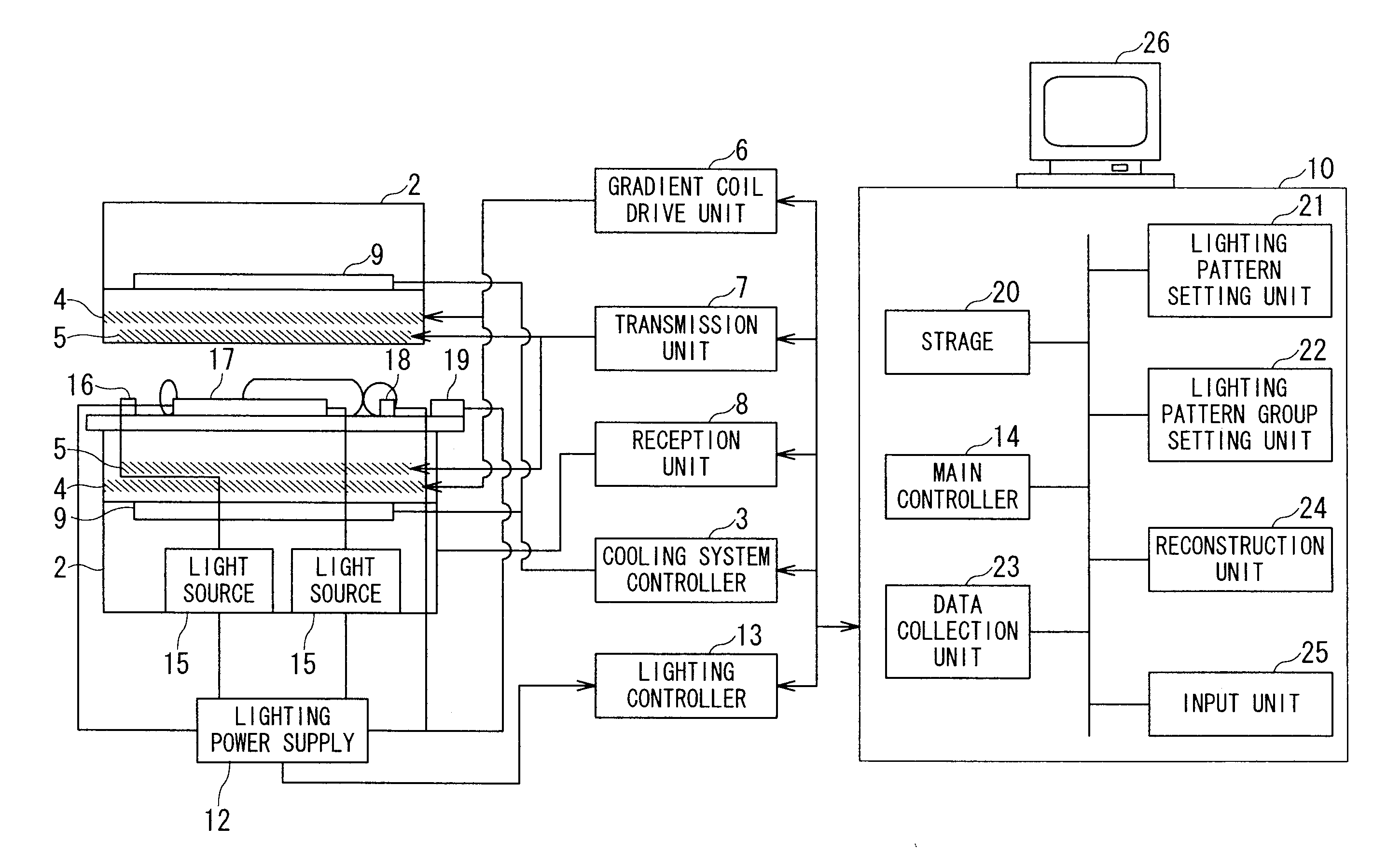
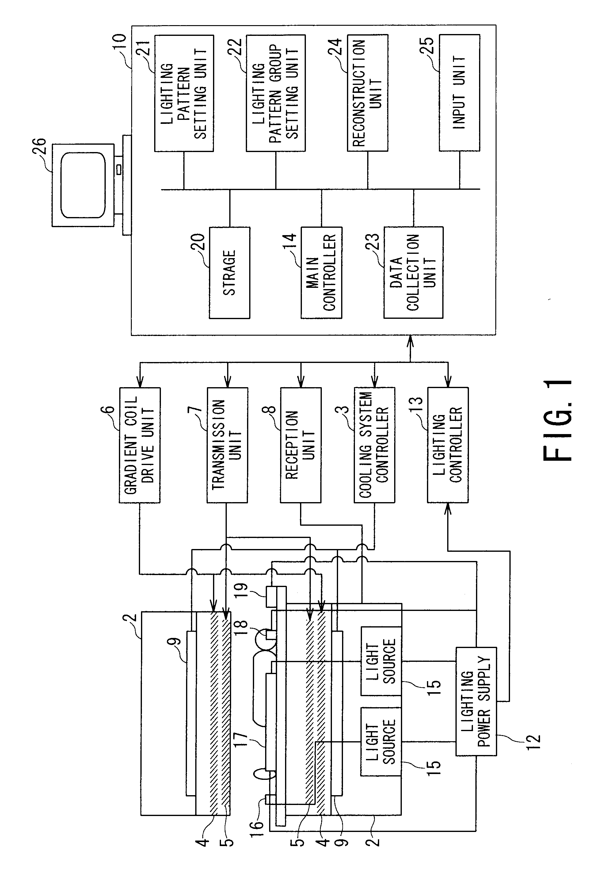
[0025]FIG. 1 is a view showing the arrangement of the MRI apparatus of the embodiment.

[0026]As shown in FIG. 1, the MRI apparatus of the embodiment includes a gantry 1 and an opening having an insertion space through which a person is inserted into the gantry 1. The MRI apparatus further includes a static field magnet 2, a cooling system controller 3, a gradient coil 4, a radio frequency (RF) coil 5, a gradient coil drive unit 6, a transmission unit 7, a reception unit 8, a cooling unit 9, an arithmetic operation unit 10, a lighting power supply 12, a lighting controller 13, and a display unit 26.

[0027]The static field magnet 2 is a magnet for generating a static field and generates a uniform static field. A permanent magnet, a superconducting magnet, and the like, for example, are used as the static field magnet 2. The static field magnet 2 is cooled by ...


PUM


Abstract

An MRI apparatus has a gantry, a bed and a lighting unit collective including a plurality of lighting units. The gantry accommodates a static field magnet configured to generate a static field, a gradient coil configured to generate a gradient magnetic field, and an RF coil configured to transmit or receive an RF pulse as well as having an opening into which a person is inserted. The bed has a removable table-top for an inside and an outside of the opening. The lighting unit group is disposed at at least one of an inside position of the opening and an outside position from which an inside of the opening can be lighted so that the lighting units can carry out lighting such that an amount of emitting light increases bit by bit from a bedside to a counter bedside opposite to the bedside across the opening.

Description

BACKGROUND OF THE INVENTION[0001]1. Field of the Invention[0002]The present invention relates to a magnetic resonance imaging (MRI) apparatus for obtaining the anatomical information and biochemical information of a person making use of a magnetic resonance phenomenon.[0003]2. Description of the Related Art[0004]There is known, as the MRI apparatus, an apparatus for displaying images as tomographic images of a distribution of nuclear spin density and a distribution of relaxation time in a desired examination part of the person by measuring signals sent from a measurement target. Since an opening (space) formed to a gantry of the MRI apparatus, through which the person is inserted, has only a size that permits the person to enter thereinto, there is a possibility that a feeling of uneasiness may be applied to the person who is subjected to an examination from that time.[0005]To cope with this problem, the MRI apparatus is provided with a lighting unit for lighting the gantry (for exa...

Claims


Application Information

Patent Timeline
IPC IPC(8): G01V3/00A61B6/04
CPCA61B5/0555G01R33/28G01R33/307G01R33/30G01R33/288A61B5/055
Inventor TAKAMORI, HIROMITSUKATSUNUMA, AYUMITSUJITA, KAZUHIKOFUKUNISHI, SOUHEI
Owner TOSHIBA MEDICAL SYST CORP
Learn More