
Virtual connection route selection apparatus and techniques

a virtual connection and route selection technology, applied in the field of communication, can solve the problems of no mechanism for re-optimizing virtual connections, no guarantee that the established path is optimal with respect to the above mentioned metrics, and the feature is currently limited to atm

Active Publication Date: 2008-08-28
GOOGLE LLC
View PDF20 Cites 47 Cited by
  • Summary
  • Abstract
  • Description
  • Claims
  • Application Information

AI Technical Summary

Benefits of technology

The invention provides a mechanism for dynamically optimizing communication traffic routes based on collected metric information, such as cost and delay, to a destination. The routing apparatus collects metric information from a remote route computation element and selects the best route based on the collected information. This allows for efficient routing of communication traffic. The invention also includes an interface for the metric information collector to communicate with the remote route computation element. The technical effects of the invention include improved efficiency and flexibility in routing communication traffic.

Problems solved by technology

Although a head-end router might attempt to find the best path based on its local information, there is no guarantee that the established path is optimal with respect to the above mentioned metrics.
There are currently no mechanisms for re-optimizing virtual connections such as end-to-end PWs based on the total end-to-end cost discovered.
This particular feature, however, is currently limited to ATM, and is also not applicable to communication systems in which centralized path computation is deployed, for example.
However, these external systems likely have a limitation of working within a single administrative boundary only, as security concerns tend to prevent network operators from sharing their network topology information so as to allow effective end-to-end optimization.

Method used


Image

  • Virtual connection route selection apparatus and techniques
  • Virtual connection route selection apparatus and techniques
  • Virtual connection route selection apparatus and techniques

Examples


Embodiment Construction

[0039]The description below refers to the following documents or the technologies disclosed therein:[0040]Farrel, et al., “A Path Computation Element (PCE)-Based Architecture”, Request For Comments (RFC)-4655, The Internet Society, August 2006;[0041]Vasseur, et al., “Path Computation Element (PCE) communication Protocol (PCEP)”, Internet-Draft, The IETF Trust, Feb. 13, 2007;[0042]Dolganow, et al., “A new object to specify a Traffic Engineering (TE) Label Switch Path (LSP) cost”, Internet-Draft, The Internet Society, October 2005.

[0043]The entire content of each of the above-referenced documents is incorporated herein by reference.

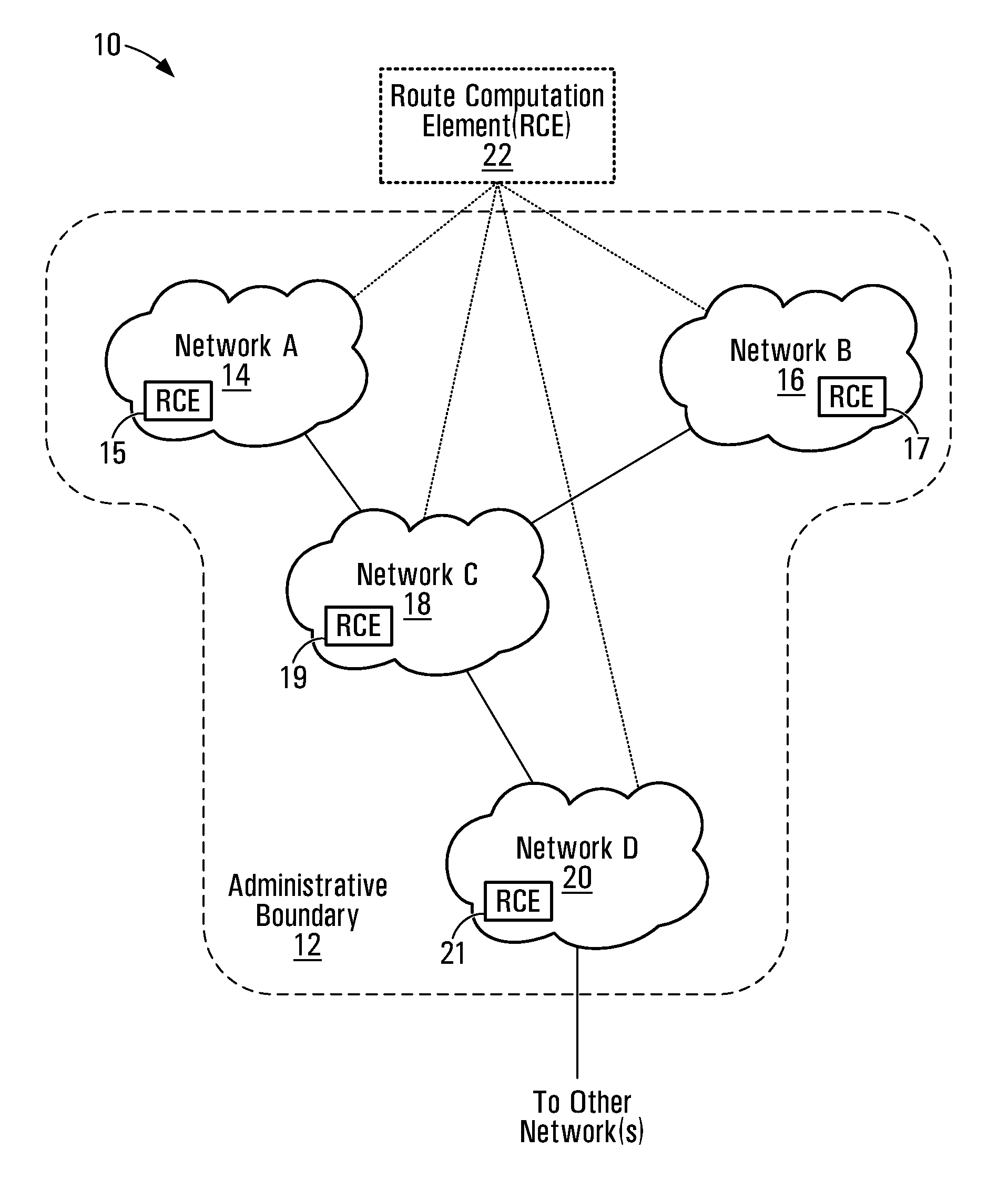
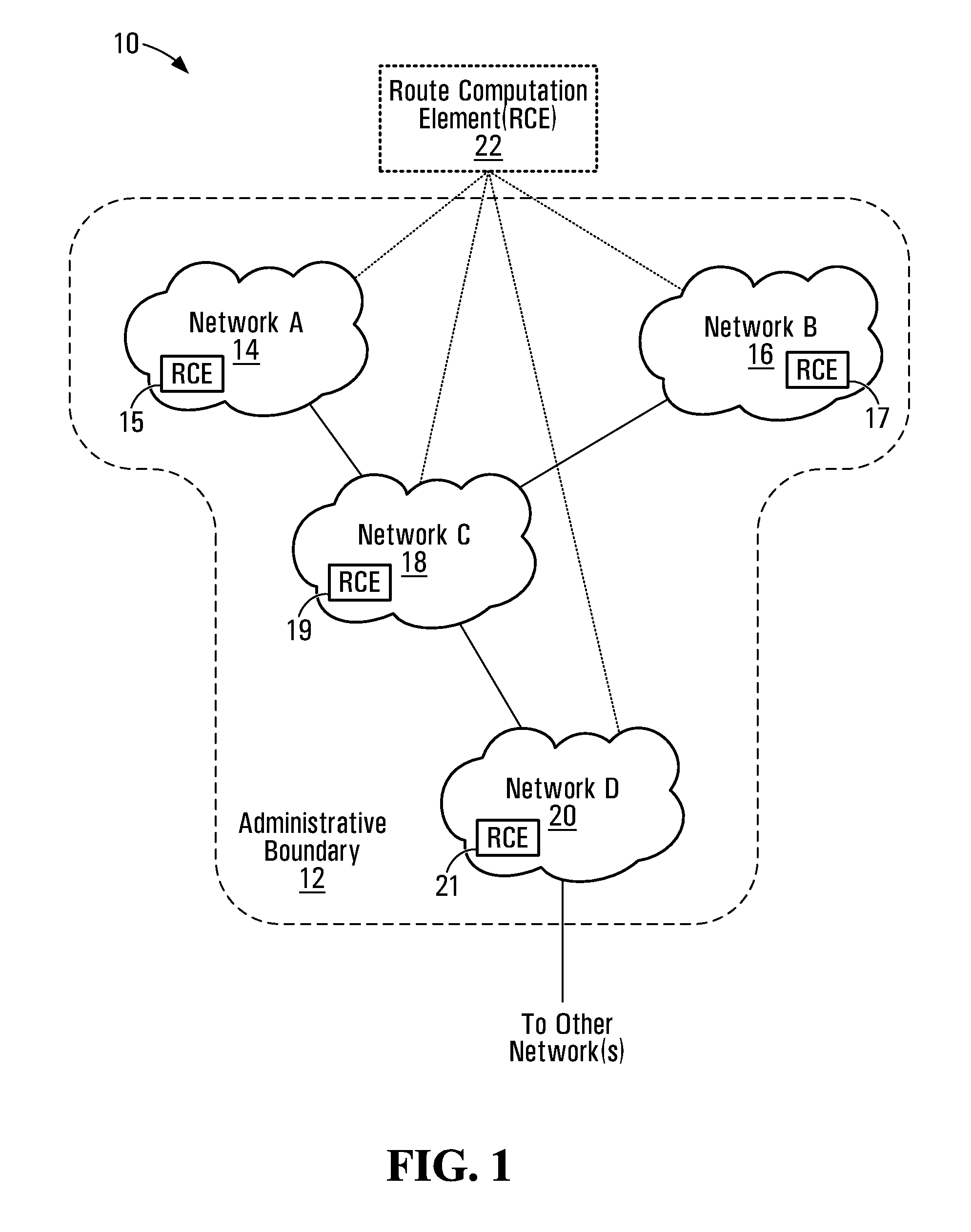
[0044]FIG. 1 is a block diagram of a communication system in which embodiments of the invention may be implemented. The communication system 10 includes several networks 14, 16, 18, 20, which may in some embodiments be different operational and / or administrative sub-domains within an administrative boundary 12. For example, the networks 14, 16, could be met...


PUM


Abstract

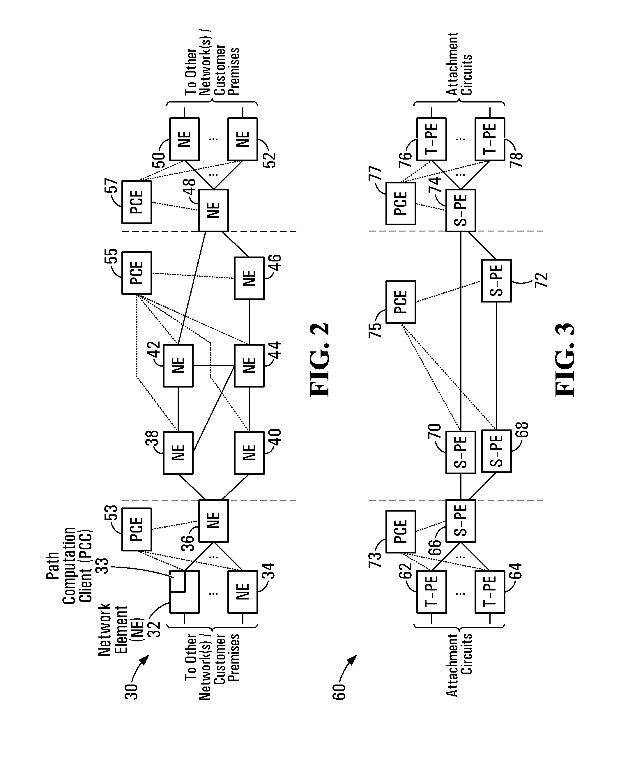
Virtual connection route selection apparatus and techniques are disclosed. At a communication traffic routing apparatus, metric information associated with multiple different routes for a virtual connection, such as a PseudoWire, toward a destination is collected. The metric information may be collected from one or more remote route computation elements capable of computing routes for virtual connections between the routing apparatus and other routing apparatus over an underlying communication system, or during actual establishment of the virtual connections, for example. An initial or re-optimized route for a virtual connection can then be selected at the routing apparatus based on the collected metric information. In some embodiments, although the virtual connection routes are paths computed by Path Computation Elements (PCEs), actual path selection decisions are distributed to routers.

Description

FIELD OF THE INVENTION[0001]This invention relates generally to communications and, in particular, to selecting between routes for virtual connections over an underlying communication system.BACKGROUND[0002]There are many circumstances in which a head end or source router cannot accurately determine the end-to-end cost and / or possibly other metrics associated with a path that is used to establish an end-to-end PseudoWire (PW). This is especially true for Multi-Segment PWs (MS-PWs) or for PWs spanning multiple operational or administrative domains such as routing domains. Although a head-end router might attempt to find the best path based on its local information, there is no guarantee that the established path is optimal with respect to the above mentioned metrics. There are currently no mechanisms for re-optimizing virtual connections such as end-to-end PWs based on the total end-to-end cost discovered.[0003]In Asynchronous Transfer Mode (ATM) systems, a Domain Based Rerouting fea...

Claims


Application Information

Patent Timeline
Patent Type & Authority Applications(United States)
IPC IPC(8): H04L12/26H04L45/02H04L45/121H04L45/50
CPCH04L12/66H04L45/02H04L45/04H04L47/10H04L45/44H04L45/50H04L45/12H04L45/124H04L45/121
Inventor AISSAOUI, MUSTAPHADOLGANOW, ANDREW
Owner GOOGLE LLC
Learn More