Slotting cutter and inserts for same

a cutting tool and insert technology, applied in the direction of shaping cutters, manufacturing tools, gear teeth, etc., can solve the problems of affecting the shape of the cutting tool, the shape may be quite complex, and the broaching method is extremely slow and costly

Active Publication Date: 2008-08-28
GREENLEAF TECH CORP
View PDF16 Cites 43 Cited by
  • Summary
  • Abstract
  • Description
  • Claims
  • Application Information

AI Technical Summary

Benefits of technology

[0012]The method may include retaining a plurality of inserts within the cutter body of the slotting cutter and retaining the metallic alloy part in a part holder which is configured to move the metallic alloy part. The inserts may be fabricated from a ceramic material. The metallic alloy part may be a turbine disk. The slotting cutter may be operated to cause the cutter body to rotate about an axis. The part holder may be positioned such that a proposed slot location on the metallic alloy part is placed in line with the p

Problems solved by technology

Secure and accurate attachment is especially important when ceramic inserts are used because cutting speeds in excess of 1000 surface feet per minute (“SFM”) are common and any slight insert movement or inaccuracy in the location of the inserts in designs where mul

Method used


Image

  • Slotting cutter and inserts for same
  • Slotting cutter and inserts for same
  • Slotting cutter and inserts for same

Examples


Embodiment Construction

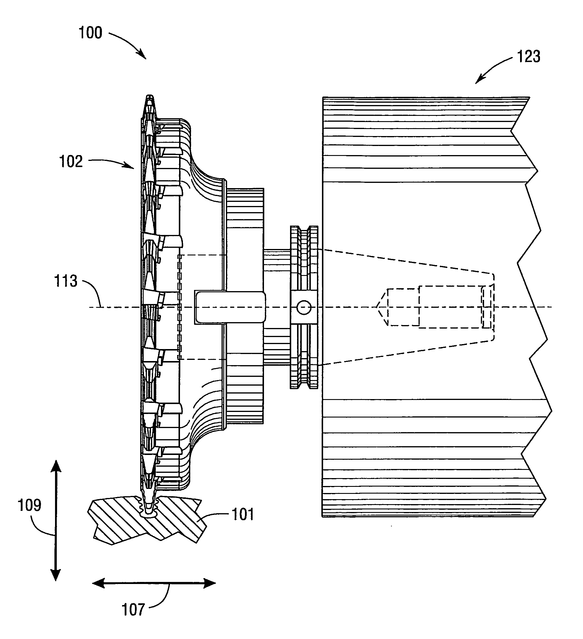
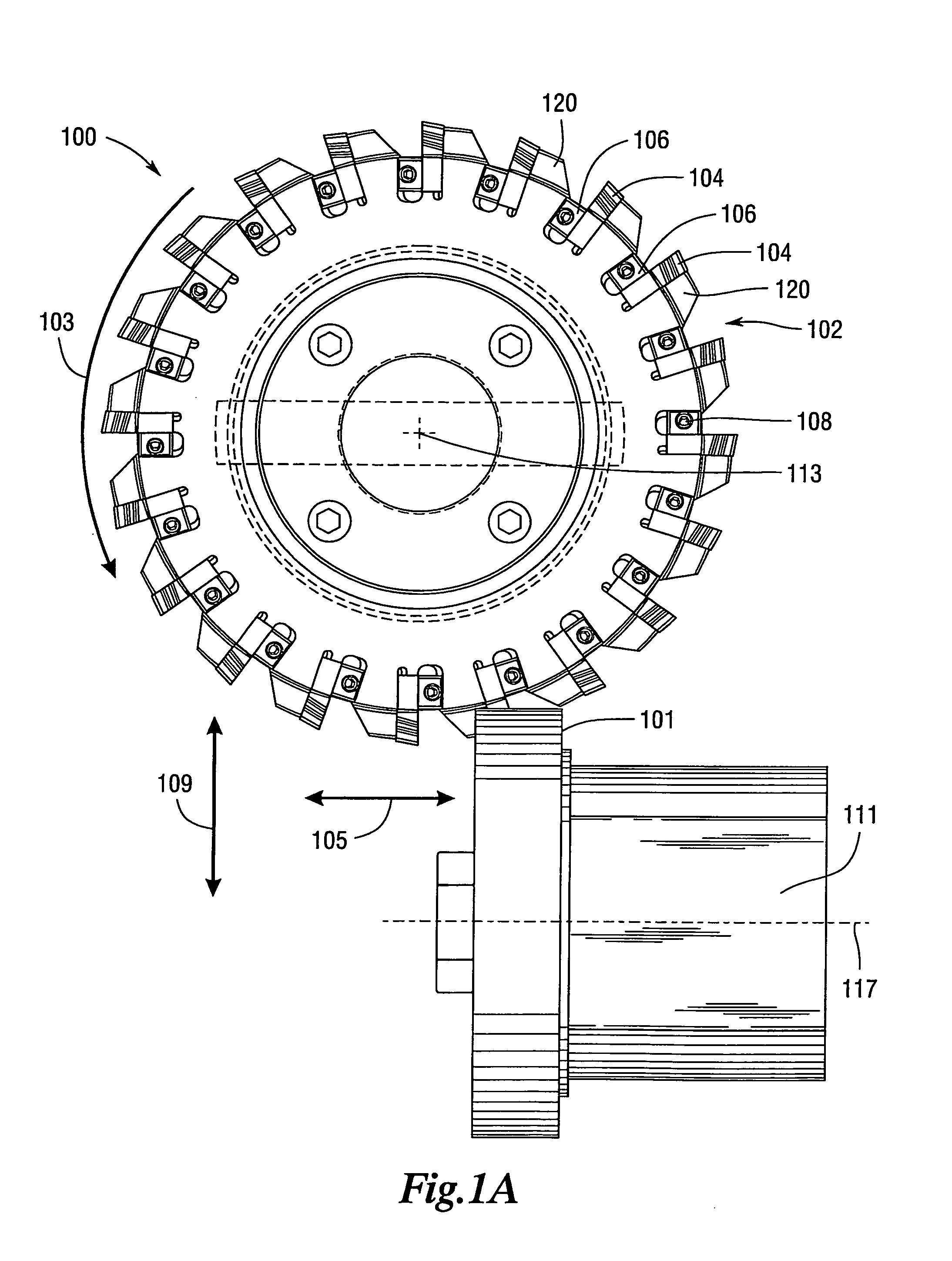
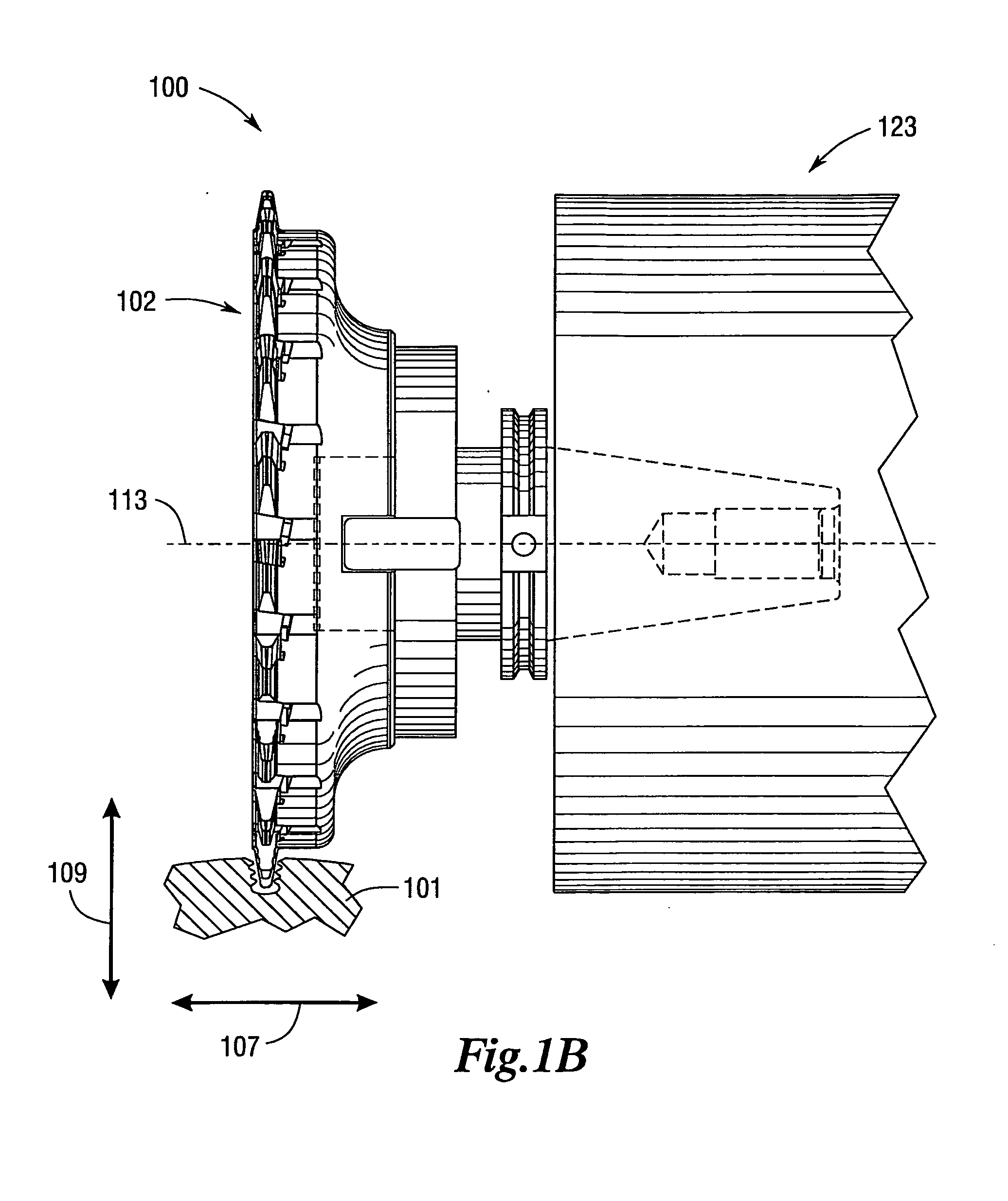
[0032]According to various embodiments, the present invention is directed to inserts, a slotting cutter assembly and methods for machining slots in metal and metallic alloy piece parts. This method may use a slotting cutter 100, as shown in FIGS. 1A-1C. FIG. 1A is a face view of an embodiment of the slotting cutter. FIG. 1B is a side view of an embodiment of the slotting cutter. FIG. 1C is a perspective view of an embodiment of the slotting cutter. The slotting cutter 100 may comprise a cutter body 102 and a drive assembly 123. In one embodiment, inserts 104 may be used in the machining process which may be securely retained within the cutter body 102. An important application where an embodiment of the present invention has proven useful is for machining of rough slots in disks used in aerospace turbine engines. These rough slots are eventually machined into finished slots which have a profile which correspond to a shape on an end of a turbine blade. As discussed previously, the tu...


PUM

PropertyMeasurementUnit
Shapeaaaaaaaaaa
Radiusaaaaaaaaaa
Widthaaaaaaaaaa

Abstract

The present invention is directed to an insert, a slotting cutter assembly and a method for machining a plurality of slots in a metallic alloy part. The insert may comprise a cutting edge, at least one primary radius, at least two secondary radii and a clearance angle. The cutting edge may form a narrow outer end at a tip of the insert and a larger width region at a distance inward from the narrow outer end. The clearance angle may extend rearward from the cutting edge. The slotting cutter assembly may comprise a plurality of inserts and a cutter body. The cutter body may comprise a plurality of retaining slots and a plurality of support portions. The retaining slot may be configured to receive the insert. The support portion may provide support for the insert.

Description

CROSS-REFERENCE TO RELATED APPLICATIONS[0001]This application claims priority to provisional application Ser. No. 60 / 891,642, entitled “Slotting Cutter and Inserts for Same” by Donald R. Hughes, filed Feb. 26, 2007, which is hereby incorporated by reference.BACKGROUND OF THE TECHNOLOGY[0002]1. Field of Technology[0003]The present disclosure relates to cutting tools, cutting inserts, and techniques for machining metals and metallic alloys. The present disclosure more specifically relates to slotting cutters and cutting inserts adapted for use with such cutters, and to techniques for machining metals and alloys using such cutting tools.[0004]2. Description of the Background of the Technology[0005]Slotting cutters are used in the metal working industry to machine full or partial slots in a part piece. A typical slotting cutter comprises a circular cutter body, and one or more high speed steel (“HSS”), carbide, or ceramic cutting inserts. These inserts are positioned around the peripher...

Claims


Application Information

Patent Timeline
IPC IPC(8): B23F5/20B26D1/00B23P15/28
CPCB23C3/30Y10T409/30952B23C5/207B23C2200/0416B23C2200/205B23C2200/367B23C2220/366B23C5/14B23C2226/18B23C2226/27Y10T407/1962Y10T409/303808Y10T409/309184Y10T409/10795Y10T407/1964Y10T407/2288B23C5/08B23C5/202
Inventor HUGHES, DONALD R.
Owner GREENLEAF TECH CORP
Why Eureka
Try Eureka